background image

16

824113

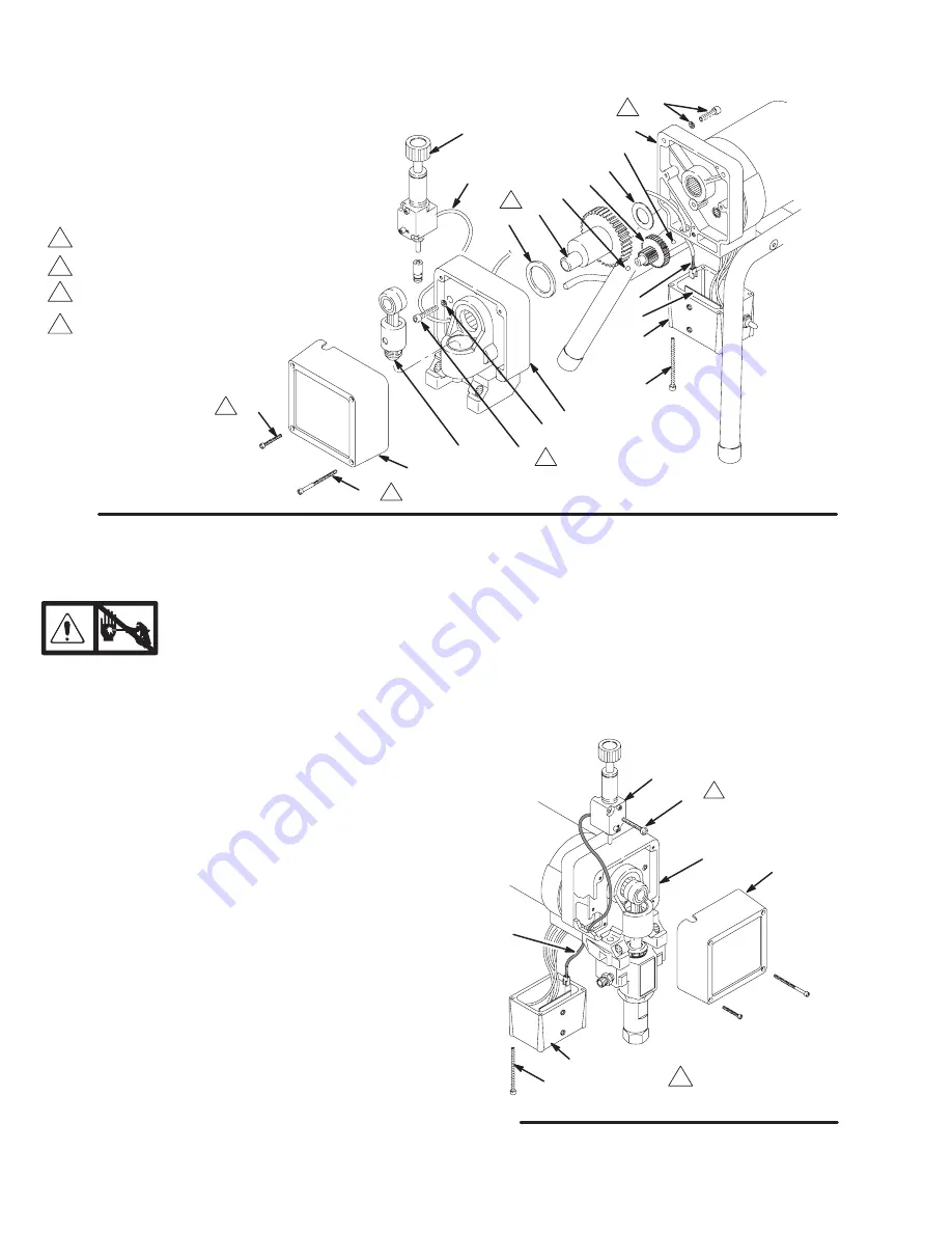
Drive Housing, Connecting Rod, Crankshaft

Torque to 2.4 N.m (21 in–lb)

Fig. 15

Quantity of three

Quantity of one

 Apply a total of 3 fl. oz.(29 cc)  
of grease to gears.

56

6

19

15

13

64

11

5,6

12a

12

12b

59

11a

4a

A

34

31

REF A

16

47

Note: Filter
not shown

02815

C

Pressure Control

Relieve pressure; page 3.

NOTE: See Fig. 16 for this procedure.

NOTE: The pressure control (64) cannot be repaired
or adjusted. If it has malfunctioned, replace it.

1.

Remove the front cover (13). Remove the screws
(56). Lower the junction box (59).

2.

Disconnect the harness connector (A) from the
motor start board (47).

3.

Remove the screws (63). Pull forward on the
pressure adjusting knob and tip the pressure
control (64) forward and up to detach it from the
drive housing (11).

4.

Guide the harness (A) through the motor and drive
housing and remove the pressure control.

5.

Guide the harness of the new pressure control
through the drive housing and motor passages.

6.

Install the new pressure control. Tip the pressure
control down and back into the drive housing (11).
Do not pinch or damage the harness (A).

7.

Loosely install the screws (63) and then torque
them to 21 in–lb (2.4 N.m).

8.

Install the front cover (13). Connect the harness
(A) to the motor start board (47).

9.

Install the junction box. Be sure no leads are
pinched against the motor or by the motor start
board.

64

63

59

56

A

13

11

Torque to
21 in–lb (2.4 N.m)

Fig. 16

02816A

Содержание 820169 D Series

Страница 1: ...Guard and SwitchTipt tool box Table of Contents Component Function and Identification 2 General Repair Information 3 Grounding 4 Troubleshooting 5 Motor Test 9 Motor Brush Replacement 10 Displacement...

Страница 2: ...fluid to be sprayed through spray gun G 50 ft 15 m Main Hose 1 4 in ID grounded nylon hose with spring guards on both ends H RAC IV Tip Guard Reverse A Clean RAC tip guard reduces the risk of fluid i...

Страница 3: ...sible solutions WARNING EXPLOSION HAZARD Motor and drive housing are very hot during operation and could burn skin if touched Flammable materials spilled on hot bare motor could cause fire or explosio...

Страница 4: ...ould cause serious injury or death 1 Models 820169 and 824175 require a 120 VAC 50 60 Hz 15A circuit with a grounding receptacle See Fig 2 2 Do not alter ground prong or use adapter Fig 2 Grounding Pr...

Страница 5: ...ecting rod pin 17 Pin must be completely pushed into connecting rod 15 and retaining spring 18 must be firmly in connecting rod groove See Fig 9 page 12 2 Push pin into place and secure with spring re...

Страница 6: ...d switch and connect volt meter between exposed terminal on switch and power cord s white wire Plug in sprayer and turn ON Meter must read 105 125 VAC for models 820169 and 824175 10 Replace ON OFF sw...

Страница 7: ...ight leakage from transducer is normal 1 Periodically remove residue from its cyl inder port See page 17 No output motor runs and pump strokes 1 Paint supply 1 Refill and reprime pump 2 For clogged in...

Страница 8: ...wires 2 For missing motor brush inspection plate gas ket see page 9 bent terminal forks or other metal to metal contact points which could cause a short 2 Correct faulty conditions 3 Motor armature f...

Страница 9: ...revolutions before coming to a complete stop If the motor does not spin freely the armature is shorted and the motor must be re placed See page 13 Armature Brushes and Motor Wiring Open Circuit Test...

Страница 10: ...ush lead terminal E off the blade connector Remove the old brush C See Fig 6 Fig 6 F G E D C B H Motor lead do not disconnect Minimum 0 5 12 5 mm Included in Brush Repair Kit236 967 4 Inspect the comm...

Страница 11: ...t full speed d Inspect the brush and commutator contact area for excessive arcing Arcs should not trail or circle around the commutator surface WARNING MOVING PARTS HAZARD Do not touch the brushes lea...

Страница 12: ...the drive housing Tap it into the alignment pins with a soft hammer Tighten the screws 21 to 50 ft lb 68 N m WARNING MOVING PARTS HAZARD Be sure the retaining spring 18 is firmly in the groove all th...

Страница 13: ...6 Also see Fig 12 6 Remove the two motor screws 5 and the lock washers 6 7 Tap the lower rear of the drive housing 11 with a plastic mallet to loosen the motor Pull the drive housing straight off the...

Страница 14: ...ply cord leads including the green wire to the grounding screw 49 4 Loosen the strain relief bushing 51 Remove the power supply cord 50 5 Install the new cord 50 in the reverse order of disassembly 6...

Страница 15: ...gears which will damage the drive hous ing if not removed The balls which are heavily covered with grease usually stay in the gear recesses but could be dislodged If the balls are not in place the bea...

Страница 16: ...ve the screws 63 Pull forward on the pressure adjusting knob and tip the pressure control 64 forward and up to detach it from the drive housing 11 4 Guide the harness A through the motor and drive hou...

Страница 17: ...tion Hose Model 820169 Relieve pressure page 3 1 Remove the drain hose 33 from the clip Remove the front cover 13 2 Pull upward on the hose 32 while unscrewing it from the inlet tube 38 The hose coupl...

Страница 18: ...sket NOTE Whenever the gasket 42a is removed re place it with a new one 3 Coat the o ring 42d with grease Press the stem into the valve body Install the spring washers and spring retainer into the val...

Страница 19: ...42c 42d Model 820169 Series D 33 20 4a 12 18 15 16 45 37 29 32 25 12b 12a 64 30 5 19 6 17 31 34 21 38 36 46 4 39 28 56 43 42 4e 44 REF 32 REF 33 11 23 63 67 74 11b 14 4g INSIDE LABEL 35 4f See detail...

Страница 20: ...05 SCREW filh 8 32 x 2 1 2 3 35 824172 LABEL identification 1 36 111612 ADAPTER tube 9 16 18 1 37 187895 LEG sprayer 2 38 192167 INLET TUBE 1 39 235004 STRAINER 1 42 235014 DRAIN VALVE KIT 1 Includes...

Страница 21: ...78 23 33 45 37 30 46 56 43 42 42a 42b 44 67 74 42c 42d 66 25 26 65 4e on opposite side 4d 96 105 90 91 100 93 39 13 31 34 14 INSIDE LABLE 21 40 36 32 17 18 15 19 63 29 20 35 OUTSIDE LABLE 19 24 28 50...

Страница 22: ...1 Includes items 42a to 42e 42a 111699 GASKET valve seat 1 42b 187615 SEAT drain valve 1 42c 224968 STEM drain valve 1 42dH 168110 O RING stem 1 42e 110110 SEALANT pipe not shown 1 43 224807 BASE val...

Страница 23: ...uminum Polyethylene Delrin Leather NOTE PTFE and Delri is a n are trademarks of the DuPont Company French 194177 Spanish 185961 German 186041 Greek 186045 Korean 186049 English 194176 Apply other lang...

Страница 24: ...e buyer agrees thatno other remedy including but not limited to incidental or consequential damages for lost profits lost sales injury to person or property or any other incidental or consequential lo...

Отзывы: