INSIDE
INSTALLATIEHANDLEIDING – P21
VERSION 0129NM02INT01
INSTALLATION MANUAL – P21 |
P21
EN
FR
07ANM20INT0
1
2. PRODUCT OVERVIEW
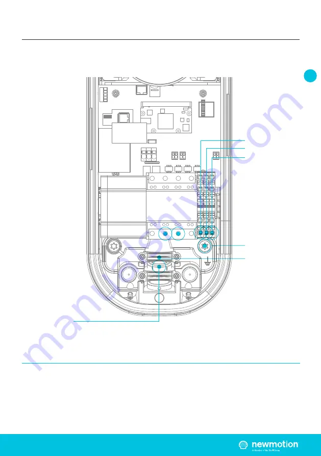
2.4.1 OVERVIEW OF CONNECTIONS
Earthing pole
Inlets for
power cables
Power cables
clamps
Phase 1NeutralEarthing
Страница 1: ...100 cm Home Advanced Edition 7 VERSION 07ANM20INT01 2020 MANUEL D INSTALLATION FR INSTRUCTION MANUAL EN...
Страница 2: ......
Страница 3: ...Table des mati res Table of contents Manuel d installation FR Pages 4 15 Instruction manual EN Pages 16 27 NewMotion Home Advanced Edition 7...
Страница 4: ...s pinces d entr e CA doivent tre quip es d une terre ininterrompue des fins de protection Assurez vous que les c bles de connexion sont quip s de fusibles et de disjoncteurs Ne remplacez jamais un l m...
Страница 5: ...nale DIN 912 taille 6 Pelle C ble d alimentation Clips de montage pour c ble DDR MCB Pour la configuration locale smartphone avec application d installation C ble UTP CAT5 ou CAT6 Outil de sertissage...
Страница 6: ...Interface utilisateur Identification Backoffice de communication Module de gestion dynamique de la puissance de communication 07A _ _ _ _ _ Home Advanced 7 phase unique 32A Home Advanced 7 3 7 kW mono...
Страница 7: ...Dimensions Poids Entr e requise Plage d humidit de fonctionnement Plage de temp rature de fonctionnement Certificats Cl ture des exigences de l armoire lectrique 55x25x30 mm 27 gr 5V DC 100mA 5 95 5...
Страница 8: ...ION 0129NM02INT01 MANUEL D INSTALLATION P8 P8 EN FR 07ANM20INT01 2 3 APER U DU PRODUIT 2 APER U DES PRODUITS Type 2S EV Prise de courant et couvercle Lecteur RFID tiquette d identification avec num ro...
Страница 9: ...ON P9 P9 EN FR 07ANM20INT01 2 APER U DES PRODUITS 2 4 1 APER U DES CONNEXIONS Port Ethernet Poteau de mise la terre Entr e de c ble de donn es UTP avec joint en caoutchouc Entr es pour les c bles lect...
Страница 10: ...01 MANUEL D INSTALLATION P10 P10 EN FR 07ANM20INT01 2 APER U DES PRODUITS 2 4 2 APER U DE L INSTALLATION DES ACCESSOIRES P1 Port pour la gestion dynamique de l nergie Entr e de c ble de donn es UTP av...
Страница 11: ...5mm Fil solide de 10 mm2 Fil de fer toronn de 6 mm2 avec embouts C ble PE le conducteur PEN n est pas autoris Electrode de mise la terre install e s par ment 100 ohms de r sistance la propagation 230...
Страница 12: ...s appropri s l paisseur du des c ble s et placez le s dans l ouverture de l entr e du c ble d alimentation Lubrifiez si n cessaire pour faciliter le passage du c ble d alimentation tape 2 Fixez le s...
Страница 13: ...rectement connect s l aide d un testeur de c ble r seau Si la LED du port P1 de la borne de recharge est bleue le module de gestion dynamique de l nergie fonctionne Si elle est rouge la cl de s curit...
Страница 14: ...rging by NewMotion demande de scanner un code QR 5 1 VERROUILLAGE DE C BLE Activez la fonction de verrouillage du c ble pour verrouiller en permanence le c ble de charge 5 2 R GLAGE DE LA PUISSANCE S...
Страница 15: ...disjoncteur m canique dans votre coffret lectrique attendez 15 secondes et rallumez le VOTRE BORNE DE RECHARGE EST IL MUNIE D UN VOYANT ROUGE CLIGNOTANT Si c est le cas cela signifie que vous utilise...
Страница 16: ...he AC input clamps must be fitted with an uninterruptible earth for protection purposes Ensure that the connection cables are fitted with fuses and circuit breakers Never replace a protection componen...
Страница 17: ...old separately DIN 912 HEX allen key Size 6 Shovel Power cable Cable mount clips RCD MCB For local configuration smartphone with Installer app UTP cable CAT5 or CAT6 RJ45 UTP cable crimp tool RJ45 con...
Страница 18: ...r interface Identification Communication backoffice Communication Dynamic Power Management module 07A _ _ _ _ _ Home Advanced 7 single phase 32A Home Advanced 7 3 7 kW single phase 16A Class I Type 2S...
Страница 19: ...IONS CONTINUED 2 PRODUCT OVERVIEW P1 DONGLE SPECIFICATIONS Stand by consumption Operating temperature range Operating humidity range Operating air pressure range Maximum mounting height socket Advised...
Страница 20: ...P20 VERSION 0129NM02INT01 INSTALLATION MANUAL P20 P20 EN FR 07ANM20INT01 2 3 OVERVIEW OF PRODUCT 2 PRODUCT OVERVIEW Type 2S EV Plug socket cover lid RFID Reader Identification label with serial numbe...
Страница 21: ...EHANDLEIDING P21 VERSION 0129NM02INT01 INSTALLATION MANUAL P21 P21 EN FR 07ANM20INT01 2 PRODUCT OVERVIEW 2 4 1 OVERVIEW OF CONNECTIONS Earthing pole Inlets for power cables Power cables clamps Phase 1...
Страница 22: ...2 VERSION 0129NM02INT01 INSTALLATION MANUAL P22 P22 EN FR 07ANM20INT01 2 PRODUCT OVERVIEW 2 4 2 OVERVIEW INSTALLING ACCESSORIES P1 Port for Dynamic Power Management UTP data cable inlet with rubber se...
Страница 23: ...nded wire with ferrules PE cable PEN conductor is not allowed Separately installed grounding electrode 100 Ohm spreading resistance 230V N 10 50Hz Cable grommets sizes Maximum cable terminal block TN...
Страница 24: ...Warning Keep charge point switched off during installation 4 4 DYNAMIC POWER MANAGEMENT MODULE The Dynamic Power Management Module package contains one Dynamic Power Management module one power adapt...
Страница 25: ...e P1 port the cable is not correctly connected 4 5 FINISHING UP Step 1 Check and make sure that the rubber seal of the casing is properly in place on the edge Step 2 Place the cover on the charge poin...
Страница 26: ...n which is included in the charge point package when the Installer App requests to scan a QR Code 5 1 CABLE LOCK Enable the cable lock feature to permanently lock the charge cable 5 2 POWER SETTING Se...
Страница 27: ...n your fuse box wait 15 seconds and turn it back on IS THERE A BLINKING RED LED LIGHT ON YOUR CHARGE POINT If so it means you are using a card which is not linked to the charge point by your installer...
Страница 28: ......