background image

Precautions

Before installation, be sure to turn off the power.

Use gloves to protect your hand from being cut by the angle
and the chassis.

Connect all the cables securely. When connecting or
disconnecting the cables, be careful not to apply stress to the
cables. (It may cause disconnection.)

Ground the human body to prevent against troubles and dust
adhesion to the LCD by static electricity. When assembling the
LCD, use a discharge blower to prevent against dust intrusion.

Be careful to the high voltage of the invertor PWB transformer.

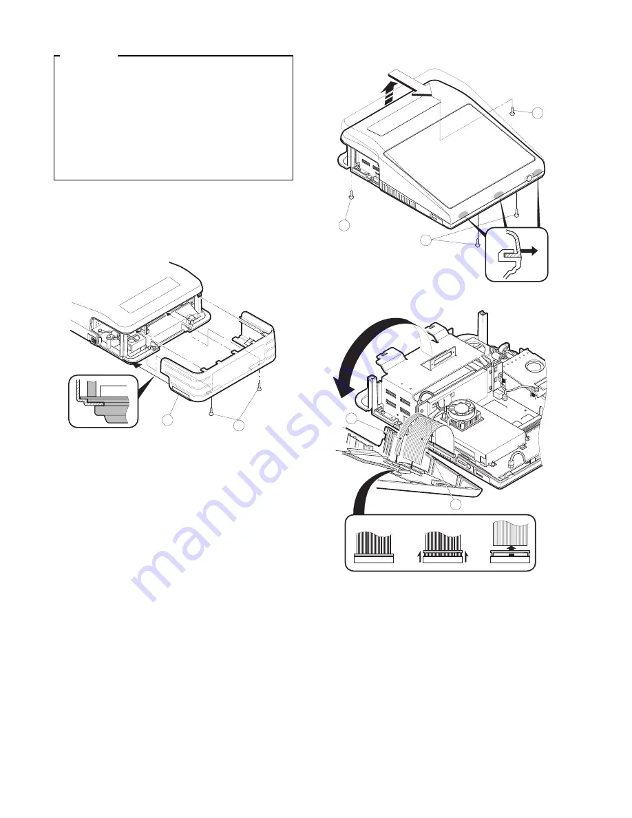
1. Removing the rear cover

1) Remove the two screws 

1

 fixed on the lower cabinet.

2) Remove the rear cover 

2

.

2. Replacing the rear cover

Install the rear cover in the reverse order of removing.

3. Removing the top cabinet

1) Remove the four screws 

1

 fixed on the lower cabinet.

2) Remove the top cabinet 

2

.

a) Lift the rear edge of the top cabinet.

b) Slide the top cabinet in the direction of arrow A and remove

three pawls of the bottom cabinet at the same time. (

Be care-

ful not to break the pawls.

)

c) Lift the top cabinet and put it straight in the direction of arrow

B. (

Be careful not to pull the cable between the KEY I/F

PWB of the top cabinet and the MAIN PWB of the Bottom
cabinet.

)

d) Pull and remove the following cables between the KEY I/F

PWB of the top cabinet and the MAIN PWB of the Bottom
cabinet.

Cable 

2

: MAIN PWB: CN15 ----- KEY I/F PWB: CN7

Cable 

3

: MAIN PWB: CN12 ----- KEY I/F PWB: CN8

(These cable connectors are of lock type. Be careful not to
damage the lock part when removing the cable.)

1

2

1

1

A

B

1

3

2

– 1 –

Содержание UP-5700

Страница 1: ...e rear cover 1 3 Removing the top cabinet 1 4 Replacing the top cabinet 3 5 Removing the power supply unit and AC cord 3 6 Replacing the power supply unit and AC cord 3 7 Removing the LCD unit 3 8 PS RAM DISK UP P02MB 4 9 F ROM DISK UP F04RB 5 10 Cautions for UP F04RB and UP P02MB 5 11 D RAM disk S O DIMM Local purchase 6 12 MCR UNIT UP E12MR 7 13 Adjusting the IRQ 10 11 on the ISA PWB 7 14 RS232 ...

Страница 2: ...er Install the rear cover in the reverse order of removing 3 Removing the top cabinet 1 Remove the four screws 1 fixed on the lower cabinet 2 Remove the top cabinet 2 a Lift the rear edge of the top cabinet b Slide the top cabinet in the direction of arrow A and remove three pawls of the bottom cabinet at the same time Be care ful not to break the pawls c Lift the top cabinet and put it straight i...

Страница 3: ...quired when the OCNCW7218RC3J s slider is broken Forcibly pulling up the slider further may cause the slider to drop and to be broken in the worst case You can change this slider part only PARTS NAME PARTS CODE SLIDER QCNCW7218RC00 2 PARTS NAME PARTS CODE LOCATION FFC CONNECTOR QCNCW7217RC3J LCD RELAY PWB CN1 How to Insert FFC 1 Open the slider to unlock position Open the slider upwards up to an a...

Страница 4: ...two screws 7 and the two earth wires 8 9 Remove the two screws 9 10 Remove the power supply cable F 11 Remove the power supply unit G 6 Replacing the power supply unit and AC cord Install the in the power supply unit and AC cord in the reverse order of removing Before installing make sure that each connector is connected se curely When connecting the AC cord to the power supply unit in assembly ti...

Страница 5: ...B a Insert the RAM disk aslant into the option ROM RAM connec tor b Push the RAM disk until the RAM disk is locked by the arms of option ROM RAM connector Up to 2 UE P02MBs can be installed to the option ROM RAM connector Be careful of the direction of RAM disk to be installed Install the RAM disk with the notch part of the PWB Figure A come right Installing the RAM disk in the wrong direction may...

Страница 6: ...for UP F04RB and UP P02MB Caution 1 Back up all data in the standard RAM disk PS RAM before installing the UP F04RB UP P02MB Caution 2 Do not insert the UP F04RB UP P02MB upside down into the con nector CN1 on the UP 5700 main PWB upside down If you try to insert the UP F04RB UP P02MB upside down the UP F04RB UP P02MB can only be inserted halfway The RAM disk on the UP 5700 may be broken Always in...

Страница 7: ...ht in the arms of the upper slot and stopped on the way to stand up Check that the UP F04RB UP P02MB stands up to about an an gle of 45 degrees by further opening the both arms of the upper slot right and left 3 Pull the UP F04RB UP P02MB out of the connector along the inclination with which the UP F04RB UP P02MB stood up Caution 4 Do not insert any general purpose RAM board additional DIM mod ule...

Страница 8: ...g the switches S1 and S2 on the ISA PWB if an option equipment is connected to the ISA slot of the ISA PWB S1 IRQ10 1 ON Connect IRQ10 to the ISA Slot 3 OFF Connect IRQ10 to GND not to the ISA Slot S2 IRQ11 1 ON Connect IRQ11 to the ISA Slot 3 OFF Connect IRQ11 to GND not to the ISA Slot 14 RS232 CENTRO I F ER A8RS Adjust the IRQ10 and IRQ11 See the 13 Adjusting the IRQ10 11 on the ISA PWB 1 Remov...

Страница 9: ...I F PWB 3 to the ISA BUS CONNECTOR 5 Fix the I F BRACKET and OPTION ANGLE 2 to the ISA BUS SHASSIS with scew 1 Only one ER 01IN PC can be installed 6 Connect the SRN cable 5 to the I F PWB 16 REAR DISPLA Y ER A8DP 1 Remove the rear cover 2 Remove the panel 1 from the cover And install the display filter 2 to the rear cover 3 Connect the display cable 3 to the main PWB 4 Install the Display PWB 4 t...

Страница 10: ...cable 1 to the drawer connector on the back of the set 4 Fix the drawer cable 1 with the cable holder 2 and tighten the screw 3 on the back of lower cabinet 5 Fix the drawer earth cable 4 to the bottom plate with the screw 5 Cable holder 2 Use the following types of cable holder supplied with the UP 5700 3N large type for the UP 5700 produced before December of 1997 2N small type for the UP 5700 p...

Страница 11: ...or Specifications D SUB9 Pin No Signal Function I O 1 CD Data Carrier Detect I 2 RD Receive Data I 3 SD Send Data O 4 ER Data Terminal Ready O 5 SG Signal Ground 6 DR Data set Ready I 7 RS Request to Send O 8 CS Clear to Send I 9 CI 5V Ring Indicate 5V I S2 1 2 3 S1 1 2 3 Main PWB S1 COM1 1 CI 3 5V S2 COM2 1 CI 3 5V S1 1 2 3 S2 S1 S2 COM1 COM2 5V 1 2 3 1 2 3 1 2 3 CI 10 ...

Страница 12: ...I 7 DR Data set Ready I 8 CS Clear to Send I 19 REMOTE POLE DISPLA Y UNIT UP P20DP 1 Install the core 6 to the display cable 1 2 Install the core 7 to the display earth cable 4 3 Connect the Display cable 1 to the remote display connector on the back of the set 4 Fix the display cable 1 with the cable holder 2 and tighten the screw 3 on the back of lower cabinet 5 Fix the display earth cable 4 to ...

Страница 13: ... used instead of the standard cable and earth wire if the UP 20DP s standard pole is removed to lower the height of the UP 20DP 1 M Earth wire S 1 1 Remove the five screws 1 2 Remove the Base angle 2 3 Remove the PWB unit 3 from the Base cabinet 4 4 Remove the display cable 5 from the PWB unit 3 5 Remove the two screws 6 6 Remove the Base cabinet 4 from the pole cabinet 7 7 Pull the Ratchet 9 atta...

Страница 14: ...ce the standard Display cable and the Earth wire with the S type cable L and wire M 20 HDD KIT DKIT 8671RCZZ The hard disk drive is a part which can be procured in the market COMPONENT LIST No NAME Q ty 1 HDD COVER A 1 2 HDD COVER B 1 3 ANGLE 2 4 HDD CUSHION 4 5 SPACER 4 6 SCREW A M3 4 4 7 SCREW C M3 8 4 8 SCREW B M3 14 4 9 WASHIER 4 F HDD CABLE 1 1 Install the HDD COVER A 1 to the HDD unit with t...

Страница 15: ...left side of the HDD unit open as shown in Figure A 6 Remove the HDD cover G from the Bottom cabinet 7 Connect the HDD CABLE F to the HDD connector CN17 on the MAIN PWB 8 Install the HDD unit to the Bottom cabinet With the SCREW A M3 8 7 A 1 pin 6 4 5 9 8 3 4 1 4 3 4 8 9 5 10 2 11 7 10 7 14 ...

Страница 16: ...stored in a retrieval system or transmitted In any form or by any means electronic mechanical photocopying recording or otherwise without prior written permission of the publisher SHARP CORPORATION Information Systems Group Quality Reliability Control Center Yamatokoriyama Nara 639 11 Japan 1998 January Printed in Japan S ...

Отзывы: