background image

34

R-7500AT

T

o

 cl

ea

the 

d

is

p

la

y

 o

f

p

res

s

 "

STOP/CLEAR

"k

ey

 f

o

s

eco

nd

s

 a

ft

er


is

 d

is

p

la

y

ed

.

9

to

ta

us

ing

 t

im

e

 (

una

b

le 

to

 b

res

et

)

10

to

ta

us

a

g

e

 co

unt

 (

una

b

le 

to

 b

res

et

)

<--- 

ini

ti

a

s

cr

een

B

y

 p

res

s

ing


 f

o

2s

ec

., 

ea

ch 

co

unt

er

ca

b

res

et

B

y

 p

us

hi

ng


ea

ch 

co

unt

er

 ca

b

ed

it

ed

.

E

rr

o

hi

s

to

ry

 (

p

rev

io

us

 10 

er

ro

rs

is

 d

is

p

la

y

ed

.

E

rr

o

o

ccur

red

D

is

p

la

y

 o

er

ro

hi

s

to

ry

B

y

 p

us

h

ing


X

3

the 

o

ld

er

 er

ro

is

 d

is

p

la

y

ed

b

y

 p

us

hi

ng


X

2

 t

he 

new

er

E

E

 xx

er

ro

is

 d

is

p

la

y

ed

.

y

y

x

x

er

ro

num

b

er

y

y

er

ro

hi

s

to

ry

(1)

the 

new

es

er

ro

r

<--- 

ini

ti

a

s

cr

een

(e.

g

.)

 E

rr

o

17,

 hi

s

to

ry

 2,

 :

 x

x

=17,

 y

y

=2

(2)

the 

s

eco

nd

 new

es

er

ro

r

(3)

the 

thi

rd

 new

es

er

ro

r

N

o

 er

ro

r


-

-

 -

-


(10)

the 

o

ld

es

er

ro

r

B

y

 p

res

s

ing


 f

o

s

eco

nd

s

,

the 

funct

io

ns

 w

hi

ch 

us

er

 ca

cha

ng

e

B

ef

o

re 

ini

ta

li

zed

M

em

o

ry

 r

es

et

a

nd

 t

he 

d

is

p

la

y

 w

h

ich 

us

er

 ca

check

 a

re 

res

et

.

88 

88

※ 

T

hi

s

 i

s

 t

o

 b

us

e

d

 a

m

a

int

ena

nce.

88

T

he 

co

nt

ent

s

 w

hi

ch 

ca

b

res

et

 a

re 

a

s

 f

o

ll

o

w

s

;


T

he 

co

nt

ent

s

 o

m

em

o

ry

 co

o

k

ing

A

ft

er

 i

ni

ti

a

li

zed


S

et

ti

ng

 o

s

o

und

 a

nd

 L

E

D

 l

ig

ht

00 

00


C

o

nd

it

io

o

m

em

o

ry

 l

o

ck

00


U

s

a

g

co

unt

 w

hi

ch 

us

eer

 ca

cl

ea

(us

a

g

co

unt

 o

m

a

nua

co

o

k

ing


 a

nd

 m

em

o

ry

 co

o

k

ing

)


U

s

ing

 t

im

w

hi

ch 

us

er

 ca

cl

ea

r


U

s

ing

 t

im

a

nd

 t

he 

w

a

rni

ng

 t

im

o

a

ir

 f

il

te

r

T

he 

fo

ll

o

w

ing

 co

nt

ent

s

 ca

no

b

cl

ea

red

.


C

o

unt

er

 f

o

m

a

int

ena

nce 

(e.

g

C

C

1)


C

o

unt

er

 w

hi

ch 

ca

no

b

res

et


E

rr

o

hi

s

to

ry

E

a

ch 

k

ey

T

es

na

m

e

D

et

a

il

 o

tes

t

ex

a

m

p

le 

o

d

is

p

la

y

MEMORY

MEMORY

MEMORY

MEMORY

POWER LEVEL

【8】

CC error indication for maint

ena

nce 

B

y

 p

res

s

ing

 f

o

2s

ec

ON/OFF of CC error indica

tion


SET MEMORY

for ma

intenace can be cha

nged. 

On

 8

On:

 CC error indicat

ion can

      be display

ed.

OFF

MEMORY

MEMORY

 8

OFF:


CC error indicat

ion can NOT

        be displa

yed.

CLEAN CAUTION

CLEAN CAUTION

SET MEMORY

SET MEMORY

※ If t

he same error occurs continuously

, it is displa

yed as one time.

Содержание R-7500AT

Страница 1: ...33 SERVICE COUNTERS 36 COMPONENT REPLACEMENT AND ADJUSTMENT PROCEDURE 39 SERVICE INFORMATION 63 MICROWAVE MEASUREMENT 63 SERVICE MANUAL S5902R7500PH T COMMERCIAL MICROWAVE OVEN R 7500AT In interests of user safety the oven should be restored to its original condition and only parts identical to those specified should be used This document has been published to be used for after sales service only ...

Страница 2: ... or other microwave gen erating devices if it is improperly used or connected All input and output microwave connections waveguides flanges and gaskets must be secured Never operate the device without a microwave energy absorbing load attached Never look into an open waveguide or antenna while the device is energized WARNING Never operate the oven until the following points are ensured A The door ...

Страница 3: ...minal with insulated pliers 5 Make the terminal metal part of the high voltage wire contact to the magnetron body with insulated pliers 6 Now the capacitors of the inverter unit are discharged 7 Reconnect the high voltage wire to the magnetron terminal after discharging WARNING Use the pliers that the portions of their handles are insulated completely to avoid an electric shock 8 Disconnect the in...

Страница 4: ... solder To reduce bit wear care should be taken to clean the bit thoroughly after each use Oven should not be run empty To test for the presence of microwave energy within a cavity place a cup of cold water on the ceram ic oven floor close the door and set the power to 100 and set the microwave timer for one 1 minute When the one minute has elapsed timer at zero carefully check that the water is n...

Страница 5: ... H x 480 D mm Two ovens stacked Cavity Dimensions 332 W x 171 5 H x 330 D mm Oven Capacity 19 litres Weight Approx 20kg Cooking Uniformity Rotary antenna system As part of a policy of continuous improvement we reserve the right to alter design and specification without notice NOTE External Equipotential Earthing Terminal Equipment has secondary earthing terminal Terminal provides external earthing...

Страница 6: ...hen saving checking or deleting memory programs It is also shown during Program Lock Oven Lamp or Audible Signal Sound setting MENU MENU will appear when selecting memory number POWER POWER will appear when selecting microwave power level X2 X3 X2 or X3 will appear when selecting double or triple quantity CLEAN CAUTION CLEAN CAUTION will appear when the cleaning of the air intake filter should be ...

Страница 7: ...it open 3 Wait for 60 seconds to discharge the high voltuge capacitor of the inverter unit 4 Isolate the switch and connect the ohmmeter to the common COM and normally open NO terminal of the switch The meter should indicate an open circuit with the door open and a closed circuit with the door closed If improper operation is indicated replace the door sensing switch 5 Reconnect all leads removed f...

Страница 8: ...operation by using the ohmmeter as follows When the door is open the meter should indicate a closed circuit When the monitor switch actuator is pushed by a screw driver through the upper latch hole on the front plate of the oven cavity with the door opened in this condition the plunger of the monitor switch is pushed in the meter should indicate an open circuit If improper operation is indicated t...

Страница 9: ...er supply cord Noise filter unit and Fuses F10A Brown wire Power supply cord Green Yellow wire Screw Blue wire Noise filter unit Blue Red Blue case Red Fuse 1 Noise filter unit Red Red Blue case Red Red Fuse 2 White Red Red ...

Страница 10: ...ue White NC Gray Black COM Red NC Gray Cabinet side COM Red NC White Monitor switch 2 Oven side Oven side Oven side Cabinet side Oven side NO Gray Blue Oven side COM Gray Red Latch switches Cabinet side Interlock switch 2 Oven side Interlock switch 1 Cabinet side Cabinet side Cabinet side ...

Страница 11: ...y unit Relay unit Control harness Connector Main harness Oven side Blue Main harness Cabinet side Main harness Connector Power unit Control harness Green Blue Bottom plate sub assy Power unit CN1 No3 Gray No1 Red CN21 No1 Green Earth wire of power unit Green No2 Red ...

Страница 12: ...AT Wiring to Relay and motor harness Control unit Current transformer CT1 Motor harness Wire lead to Relay Blue Ribbon cable of FPC Control unit Connector CNF of control harness Connector CNG of control harness ...

Страница 13: ...verter unit contain circuitry capable of producing very high voltage and current contact with the heat sinks FA terminal F terminal printed wiring board and other portions may result in a severe possibly fatal electrical shock Magnetron 2 Inverter unit 1 Inverter unit 2 Magnetron 1 Both of Magnetron 1 and Magnetron 2 FA terminal back plate side Red with white case F terminal cavity assy side Red w...

Страница 14: ...tor of MGT thermistor 1 Connector of control harness Wiring of connection at rear side Wiring to MGT thermistor 1 Connect the connector of MGT thermistor 1 to the connector of the control harness Insert the connected connectors into the hole of the rear duct Put the cloth tape on the portion where the connectors are inserted at the rear duct ...

Страница 15: ...R 7500AT 15 Magnetron 1 Rear duct Control harness Cloth tape Wiring with tape at rear side Red Red White Gray Blower motor 1 Blower motor 1 ...

Страница 16: ...16 R 7500AT Blower motor 2 Gray Blower motor 2 Red ...

Страница 17: ...R 7500AT 17 Antenna motor 2 Antenna motor 1 Antenna motor 2 Cavity assy top plate Blue White Red Red Antenna motor 1 Motor harness Gray Motor harness Red Wiring Antenna motor ...

Страница 18: ... fuse 120 Main harness Exhaust duct A Control harness Exhaust thermistor Inverter harness LED Light Cavity assy Left side PWM harness Exhaust temp fuse 120 Exhaust duct A Gray Main harness Control harness Harness of exhaust thermistor Gray Gray ...

Страница 19: ...otor 2 Wire holder Exhaust duct A Wire holder Cavity assy Left side Positions of wire holders At the following eight 8 positions hold the wire leads with wire holders so that the wire leads do not touch to any sharp edges ...

Страница 20: ...20 R 7500AT Wire holder Exhaust duct A Antenna motor 2 Cavity assy Top side Wire holder Wire holder Wire holder Wire holder Separate angle Screw Inverter cover R HV wire assy ...

Страница 21: ...h wires of inverter unit 2 Secure the two 2 earth wires wires of the inverter unit 2 to the inverter support AG L and the bottom plate sub assy with the two 2 screws After the earth wire is fixed to the bottom plate sub assy with the one 1 srew hold the earth wire to the inverter supp AG L with the cloth tape as shown in the picture This is to prevent that the earth wire is caught in the outer cas...

Страница 22: ...al cover and the waveguide of the cavity assy with the two 2 screws After the earth wire is fixed to the waveguide of the cavity assy hold the earth wire to the thermal cover with the cloth tape as shown in the picture This is to prevent that the earth wire is caught in the outer case cabinet Thermal cover Earth wire of inverter unit 1 Screw Cloth tape ...

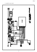
Страница 23: ... MOTOR RELAY 18P CONNECTOR D B6 B7 A5 FUSE 1 F10A FUSE 2 F10A RELAY UNIT LED LIGHT B3 B4 B2 B1 MONITOR SWITCH 2 MONITOR SWITCH 1 INVERTER UNIT 1 M AC A3 A1 MAGNETRON 1 F M AC A3 A1 INVERTER UNIT 2 F MAGNETRON 2 G4 G5 G6 G8 G10 G7 G9 CONTROL UNIT G1 G2 G3 MGT THERMISTOR 1 MGT THERMISTOR 2 EXHAUST THERMISTOR INTERLOCK SWITCH 1 INTERLOCK SWITCH 2 VS2 PWM2 VS1 PWM1 18P CONNECTOR F 1 SCHEMATIC DIAGRAM ...

Страница 24: ...D21 C13 CN21 2 1 C24 F21 D7 R11 C7 C9 C10 C8 PC1B 4 3 R7 R22 C21 T1 12 2 10 8 7 4 3 FB1 D6 R6 C6 R3 R4 R5 C5 C1 CN1 3 2 1 C14 C11 C12 R1 R2 TH1 R10 D5 IC1 5 3 2 1 4 6 8 7 NC DRV CS FB ADJ VCC HV GND VZ3 D21 D8 L1 D1 R9 D2 D4 D3 Q1 R8 ZD2 VZ1 ZD1 F1 1 2 VZ2 CD1 2 POWER UNIT CIRCUIT ...

Страница 25: ...R 7500AT 25 3 INVERTER UNIT CIRCUIT R67 33 ...

Страница 26: ...ED 3 D200 R200 L200 10K LED LAMP MG TH ON 24V 18 GND 17 MAG2 RY MAG1 RY LED LAMP R105 R104 C22 LED LAMP M3 P0_7 P1_3 P2_0 P1_1 P1_0 P1_2 CN N SCL SDA 2 1 VDD 3 GND 4 停止 取消 Q46 MAG1 TH MAG2 TH 300KF R170 Q111 DTA143EKA C70 C73 330pF 50V DTC143EKA 4 RELAY UNIT AND CONTRL UNIT CIRCUITS 火力 选择 记忆 烹调 SEG12 SEG11 SEG10 SEG9 SEG8 SEG7 SEG6 SEG5 SEG4 SEG3 SEG2 SEG1 SEG0 COM2 P0_5 AN8 AN7 P0_2 AN5 AN4 VL1 V...

Страница 27: ...LIGHT FPC POWER SUPPLY CORD MISADJUSTMENT OF SWITCHES OPENED WIRE HARNESS BLOCKED VENTILATION OPENINGS CHECK OF LIGHT SETTING EXHAUST TEMP FUSE 120 PLUGGED IN AND DOOR OPENED Display does not show anything Any key is not accepted Oven does not go into a cook cycle Oven cooks slowly Oven stops in a cook cycle Oven does not count the cooking time down LED light does not light Blower motor does not o...

Страница 28: ... circuit to drive the magnetron 1 2 Parts for the circuit to drive the magnetron 2 Magnetro 1 Magnetro 2 Inverter unit 1 Inverter unit 2 Interlock switch 1 Blue cases Interlock switch 2 White cases Monitor switch 1 Blue cases Monitor switch 2 White cases Fuse 1 F10A Blue cases Fuse 2 F10A White cases Blower motor 1 Blower motor 2 Antenna motor 1 Antenna motor 2 MGT thermistor 1 MGT thermistor 2 ...

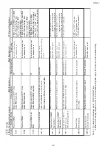
Страница 29: ...ten data is different from read data is done MGT thermistor 1 is open or short MGT thermistor 1 When power is on Open when power is on or EE 16 Right after heating start right after heating start Short right after heating start MGT thermistor 2 is open or short MGT thermistor 2 When power is on Open when power is on or EE 26 Right after heating start right after heating start Short right after hea...

Страница 30: ...30 R 7500AT 2 Error for maintenance 37 4 It can be selected by test mode 8 if CC error is indicated or not SET MEMORY ...

Страница 31: ...ns 1 negative and 3 positive 2 Replace the magnetron 1 Check is finished In this case check the high voltage diodes D120 and D121 of the inverter unit for a short circuit Correct the wiring Completely insert the harnesses Is wiring on the high voltage side correct Have the terminals been completely inserted Is there continuity between the magnetron terminals Is there a short circuit between the ma...

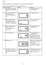
Страница 32: ...leven times can be heard select the power level to 3 500W or its equivalent 4 By pressing the number The key input sound keys 4 and 5 can be heard set the heating time to 45 seconds 5 Press the start key The key input sound can be heard LED light is turned on Antenna motors rotate Blower motors rotate Microwave heating starts 6 Heating is over Information sound sounds Blower motors rotate for a wh...

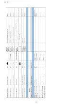
Страница 33: ...he maintenance When 1 is pressed once the contents of memory No 1 is displayed When 1 is pressed twice the contents of memory No 11 is displayed When 1 is pressed third time the contents of memory No 21 is displayed 1 using time of magnetron 1 hour difference between 11 and 12 xx yy 11 total using time of magnetron 1 hour 21 using time of magnetron 1 hour when exchanging it xx yy hour 2 using time...

Страница 34: ...can check are reset 88 88 This is to be used at maintenance 88 The contents which can be reset are as follows The contents of memory cooking After initialized Setting of sound and LED light 00 00 Condition of memory lock 00 Usage count which useer can clear usage count of manual cooking and memory cooking Using time which user can clear Using time and the warning time of air filter The following c...

Страница 35: ...clamp the brown wire of the power supply cord And then measure the current 2 Place the container filled with 1000cc water at the center of the flat table of the oven And close the door 3 Press STOP CLEAR key 4 Press X3 key 5 Press POWER LEVEL key 6 Open and close the door 7 Press 8 key Microwave cooking will start 8 Adjust the current with X2 key or X3 key so that the center of the ammeter s defle...

Страница 36: ...hanged input the count using time or using count of the old control unit into the new control unit Input procedure 1 Before exchanging the control unit wirte down the datas of memory No 3 4 5 6 7 9 10 11 12 13 14 15 16 17 21and 22 of the old control unit To know the datas set the test mode and refer to the Key of the service counter table then input the key 2 After installing the new control unit ...

Страница 37: ... 59minutes and 59seconds Pressing 2 third times Memory No 22 Total using time of magnetron 2 when exchanging it 12 3456 0 key Number keys key 999999hours 59minutes and 59seconds Pressing 3 once Memory No 3 Magnetron maintenance time CC1 CC2 1234 1250 key Number keys key The time which CC1 CC2 or CC3 should be displayed is memorized 9999hours Pressing 3 twice Memory No 13 Magnetron maintenance time...

Страница 38: ...d 59seconds Pressing 0 once Memory No 10 Total usage count unable to be reset 12 3456 0 key Number keys key Unable to be reset 999999 times Error history After setting test mode carry out following procedure Setting Test mode Newest error 1 EE 17 Pressing X3 once or 2 nine times Second newest error 2 EE 17 Pressing X3 nine times or X2 once Tenth newest error Oldest error 10 EE 17 User counter With...

Страница 39: ...There are defective parts in the door interlock system 6 There are defective parts in the microwave generating and transmission assembly 7 There is visible damage to the oven Do not operate the oven 1 Without the RF gasket Magnetron 2 If the wave guide or oven cavity are not intact 3 If the door is not closed 4 If the outer case cabinet is not fitted To prevent an electric shock take the following...

Отзывы: