27
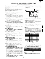
R - 2 2 A T
R-23AM
R - 2 4 A T
PAD ORDER
DISPLAY
PHONE
(Door close)
•
SET
•
SET
"NUMBER"
•
(within 2 sec.)
1
NUMBER 1
• 0
5
NUMBER 1
• 5
SET
"NUMBER"
•
SET
•
OTHER CHECKING AND CLEARING PROCE-
DURE FOR R-24AT / R-22AT
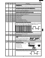
1) To check the contents of defrost.
" " : Flicker / : 0.1 sec BUZZER
PAD ORDER
DISPLAY
PHONE
(Door close)
•
CHECK
"NUMBER"
•
CHECK
DEFROST
1 0.20 DEF CHECK
(A)
DEF CHECK
1 20 POWER
(+ - B) 50%
2 0.13 DEF CHECK
(A)
DEF CHECK
2 30 POWER
(+ - B) 30%
DEF CHECK
3 5 POWER
20%
(Repeat)
CHECK
•
#1 : No key entry signal.
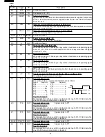
2) How to clear all counter(user and service) and total
cooking time and used time of filter.
PAD ORDER
DISPLAY
PHONE
(Door close)
•
SET
•
SET
"NUMBER" •
DOUBLE
"NUMBER" • DOUBLE
CHECK
"NUMBER" • DOUBLE
VOLUME
"NUMBER" • DOUBLE
SET
•
Memory No.
Cook Time
Output Power
1
5 sec.
100%
2
10 sec.
100%
3
20 sec.
100%
4
30 sec.
100%
5
40 sec.
100%
6
50 sec.
100%
7
1 min.
100%
8
1 min. 15 sec.
100%
9
1 min. 30 sec.
100%
10
2 min.
100%
11-20
0 sec.
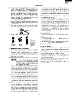
3) How to enter the EEPROM pad.
Enter the EEPROM data into the memory pads, 3, 4,6, 8,
9, 11, 12, 13, 14, 15 and 20, referring to following example
and the table of EEPROM data.
Example: Suppose the EEPROM dada "2235" is entered
in to the memory pad 3.
" " : Flicker / : 0.1 sec BUZZER
PAD ORDER
DISPLAY
PHONE
(Door close)
•
CHECK
"NUMBER"
•
CHECK
CHECK
#2
8268
"CHECK"
(User"s Total Counts)
#1
VOLUME
#2
8268
"CHECK"
VOLUME
#2
8268
"CHECK"
DOUBLE
#3
xxxxxx "CHECK"
QUANTITY
(Total Counts of Service)
3
3030 "CHECK"
SET
0 "CHECK"
2, 2, 3, 5
2235 "CHECK"
x4
SET
2235 "CHECK"
CHECK
•
#1: Denotes the procedure for the servicer to disable clearing.
This procedure is instructed to service personnel only and
is excluded from the operation manual.
#2: If the IC-2 is exchanged, 0 should be indicated instead of
8268. But if the control unit is exchanged, 0 is not always
indicated.
#3: Total counts of Service, 6 figures will be displayed.
Enter the memory information into the memory pads 1
~10 referring to above example. The memory information
are given below.
Table of EEPROM data
Memory
pad
Data
Contents
3
2 2 3 5 Hiher temperature limit setting of magn-
etron thermistor detection.
4
0 0 0 0 Constant setting of fan lock detection.
6
0 1 0 0 Time setting of fan lock detection.
8
3 2 0 0 Hiher temperature limit setting of ex-
haust air detection.
9
0 0 0 0 Constant setting of fan lock detection.
11
0 0 0 0 Constant setting of magnetron thermis-
tor detection.
12
0 0 0 0 Constant setting of magnetron thermis-
tor detection.
13
0 0 0 0 Constant setting of magnetron thermis-
tor detection.
14
0 0 0 0 Constant setting of magnetron thermis-
tor detection.
15
1 5
Interval time setting of magnetron ther-
mistor detection.
20
0 0 0 0 Switching level setting of magnetron ther-
mistor detection.


