background image

26

F

Initialisation (Restauration)/Réglage des restrictions des fonctions

Vous pouvez restaurer le contraste, la qualité de l’image et d’autres réglages en leurs valeurs préréglées
à la sortie d’usine, spécifier si les diodes d’alimentation s’allument, et permettre la commande via
RS-232C (voir à la page 37) parmi d’autres fonctions.

2.

 Sélectionnez et réglez les options que vous voulez.

3.

 Appuyez sur 

 pour retourner à l’écran normal.

1.

 Après avoir appuyé sur 

 pendant environ 5 secondes, appuyez sur 

, et sur 

dans cet ordre.

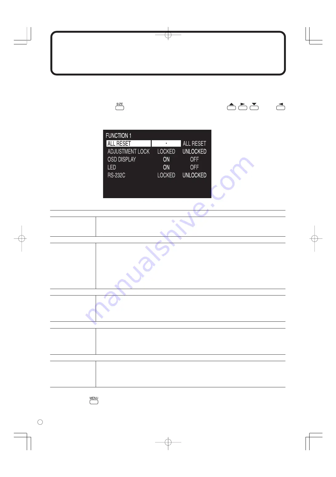
L’écran FUNCTION 1 va apparaître.


[ALL  RESET] <TOTAL RESET>

    Fonction 

Restaure tous les réglages du moniteur en leurs valeurs préréglées à la sortie d’usine.


Après l’initialisation (restauration), mettez l’interrupteur principal hors tension puis 


remettez le sous tension.


[ADJUSTMENT  LOCK] <OSD VERROUILLÉ> 

    Fonction 

Spécifie s’il verrouille les réglages tels que ADJUSTMENT <AJUST> et WHITE BALANCE 


<BALANCE COULEUR>. Lorsque le verrouillage est mis en place, la télécommande ne 


peut pas réaliser d’autres opérations que mettre en/hors tension (bouton POWER) et 


afficher l’écran FUNCTION 1 <FONCTION 1>.

    Par défaut 

UNLOCKED <DÉVERROUILLÉ>

    LOCKED <VERROUILLÉ>  Verrouille le réglage.
    UNLOCKED <DÉVERROUILLÉ>  Déverrouille le réglage.
 

[OSD  DISPLAY] <OSD>

    Fonction 

Cache/affiche les menus. L’écran FUNCTION 1 <FONCTION 1> ne peut pas être caché.

    Par défaut 

ON

    ON 

Affiche les menus.

    OFF 

Cache les menus.


[LED]

    Fonction 

Spécifie l’allumage de la diode d’alimentation.

    Par défaut 

ON

    ON 

La diode d’alimentation s’allume.

    OFF 

La diode d’alimentation ne s’allume pas.


[RS-232C]

    Fonction 

Spécifie si la commande via le réglage RS-232C est autorisée (voir à la page 37).

    Par défaut 

UNLOCKED <DÉVERROUILLÉ>

    LOCKED <VERROUILLÉ>  Désactive la commande via le réglage RS-232C.
    UNLOCKED <DÉVERROUILLÉ>  Active la commande via le réglage RS-232C.

Содержание PN-655

Страница 1: ...ENGLISH FRANÇAIS PN 655U LCD MONITOR MONITEUR LCD OPERATION MANUAL MODE D EMPLOI ENGLISH E1 FRANÇAIS F1 ...

Страница 2: ......

Страница 3: ...HOCK DO NOT REMOVE COVER NO USER SERVICEABLE PARTS INSIDE REFER SERVICING TO QUALIFIED SERVICE PERSONNEL The lightning flash with arrowhead symbol within an equilateral triangle is intended to alert the user to the presence of uninsulated dangerous voltage within the product s enclosure that may be of sufficient magnitude to constitute a risk of electric shock to persons The exclamation point with...

Страница 4: ...he equipment is operated in a commercial environment This equipment generates uses and can radiate radio frequency energy and if not installed and used in accordance with the instruction manual may cause harmful interference to radio communications Operation of this equipment in a residential area is likely to cause harmful interference in which case the user will be required to correct the interf...

Страница 5: ...t place the product on a bed sofa rug or other similar surface since they can block ventilation openings Do not place the product in an enclosed place such as a bookcase or rack unless proper ventilation is provided or the manufacturer s instructions are followed 9 Power cord protection The power cords must be routed properly to prevent people from stepping on them or objects from resting on them ...

Страница 6: ...sure that the product is in proper operating condition 17 Wall mounting When mounting the product on a wall be sure to install the product according to the method recommended by the manufacturer 18 Heat sources Keep the product away from heat sources such as radiators heaters stoves and other heat generating products including amplifiers WARNING This is a class A product In a domestic environment ...

Страница 7: ... damage it Do not use in places where the monitor will be subject to direct sunlight near heating equipment or anywhere else where there is likelihood of high temperature as this may lead to generation of excessive heat and outbreak of fire The Power Cord Do not damage the power cord nor place heavy objects on it stretch it or over bend it Also do not add extension cords Damage to the cord may res...

Страница 8: ...y Stand 20 Basic Operation Turning Power On Off 21 Main power switch 21 Turning power on off using remote control 21 Remote Control Unit 22 Menu Items 23 Menu option selection 23 Menu screen explanation 25 Initialization Reset Functional Restriction Setting 26 Settings and Adjustments 27 Adjustments for PC screen display ANALOG 35 Set up information ANALOG 36 PC Operation PC Operation 37 PC connec...

Страница 9: ... component should be missing please contact your dealer Power cord 1 CD ROM 1 Utility Disk for Windows AA size battery 2 Remote control unit 1 Temporary stand fixed 1 See pages 8 and 19 Liquid Crystal Display 1 Sharp Corporation holds authorship rights to the Utility Disk program Do not reproduce it without permission Approx 13 1 feet 4 m QACCU1034MPPZ Operation manual 1 Stand hole protection cove...

Страница 10: ...bject such as a pen Power LED See page 21 LCD panel Temporary stand See pages 19 and 20 The shape of the stand may change without prior notice Relationship between the input signals and input terminals You can use the remote control to change the input terminals used for video and audio signals See page 22 Video input Input mode See page 25 DIGITAL ANALOG COMPONENT VIDEO PC digital RGB input termi...

Страница 11: ... See page 16 Composite video input terminal See page 15 External speaker terminals left See page 16 Audio input terminals See pages 14 and 15 Audio output terminals See page 15 PC audio input terminal See pages 12 and 13 Handles See pages 19 and 20 RS 232C output terminal See pages 19 and 38 Component video input terminal See page 14 RS 232C input terminal See pages 19 37 and 38 PC analog RGB inpu...

Страница 12: ...on See page 22 MODE button See page 22 VOL buttons See page 22 BRIGHT buttons See page 22 INPUT button See page 22 Signal transmitter MENU button See page 23 SIZE button See page 22 Cursor control buttons See page 23 You can use this button when the menu is not displayed You can use this button when the menu is not displayed You can use this button when the menu is displayed ...

Страница 13: ...o the top bottom right left of the remote control sensor If the remote control unit does not work well The remote control unit may not work properly if the remote control sensor is under direct sunlight or strong lighting In such cases change the angle of the lighting or operate the remote control unit closer to the remote control sensor Objects between the remote control unit and the remote contr...

Страница 14: ...igital signal DVI cable commercially available Connection with computers that have an output terminal DVI D 24 pin or DVI I 29 pin conforming to DVI is possible However images may not display properly depending on the computer Connect with an audio output terminal on your computer using a PC audio cable commercially available Select the input mode DIGITAL for this connection See page 22 Digital si...

Страница 15: ...when you change the setting of the PC See page 35 Audio Display Output terminals on connected equipment PC audio input terminal PC analog RGB input terminal PC analog signal RGB cable commercially available PC audio cable commercially available Rear view Auto detects sync signal type Sync signal presence is detected in this order Composite sync Horizontal Vertical separate and Sync on green If for...

Страница 16: ...A cable commercially available Select the input mode COMPONENT for this connection See page 22 Rear view Output terminals on connected equipment Component video Audio Right Left Red Right White Left Red Right White Left Audio RCA cable commercially available Component BNC cable commercially available Y Cb Pb Cr Pr Y Cb Pb Cr Pr Component video input terminal Audio input terminals Connecting Periph...

Страница 17: ... cable commercially available The audio output varies depending on the input mode selection When the input mode is DIGITAL or ANALOG the audio from the PC audio input terminal is output When the input mode is COMPONENT or VIDEO the audio from the audio input terminals is output The output volume is set to the value controlled with the volume adjustment See page 22 PC digital RGB DVI D output termi...

Страница 18: ...g the speaker cables 1 While pushing the tab insert the tip of the cable 2 Release the tab Rear view Make sure to connect the speaker terminal and cable polarity properly The speaker terminals have plus and minus polarity Plus is red and minus is black The speaker cables are also divided into plus and minus When connecting the left right speakers be sure to connect the plus minus terminals with th...

Страница 19: ...ower supply other than the one specified may cause fire 1 Confirm that the main power switch is set to OFF O 2 Plug the power cord supplied into the AC input terminal 3 Plug the power cord supplied into the AC power outlet Main power switch OFF O position Plug to the AC input terminal Power outlet Power cord supplied AC input terminal Plug to power outlet Disconnecting the power cord 1 Confirm tha...

Страница 20: ...ultiple monitors 4 units max can be connected in a daisy chain using the provided PC digital RGB input terminal and PC digital RGB output terminal Connection example Second monitor First monitor Multiple monitors cannot be connected in a daisy chain for audio Connect the external audio amplifier commercially available to the audio output terminals The length of the digital signal DVI cables or sur...

Страница 21: ... mount this monitor in different ways such as hanging it on a wall so be sure to rely on an authorized Sharp dealer for installation work You should never perform any of this work yourself Our company will bear no responsibility for accidents or injuries caused by improper mounting or handling This monitor is fixed to the temporary stand when shipped from the factory Please note that this stand is...

Страница 22: ... it from falling down and remove the upper and lower stand fixing screws 4 2 Lift the monitor by holding it with the handles and the underside of the unit 3 When the installation is complete attach the supplied stand hole protection covers as necessary The temporary stand is specifically designed for this monitor Do not use the removed stand for other devices Store the removed screws together with...

Страница 23: ...e monitor enters input signal waiting mode The power LED flashes green If the monitor is in this mode and you press the POWER button on the remote control unit the monitor enters standby mode If the remote control is not available you can turn on off by pressing the power switch beside the power LED with a sharp object see page 8 Turning power on off using remote control Main power switch ON posit...

Страница 24: ...automatically disappears Sound is muted when volume is set to 0 BRIGHT Backlight adjustment Pressing or displays the BRIGHT menu when the menu screen is not displayed B R I G H T 15 Press to increase the brightness of the screen and to decrease the brightness of the screen If you do not press any buttons for about 4 seconds the BRIGHT menu automatically disappears SIZE Screen size selection Each t...

Страница 25: ... RIGHT Selects a desired item on the screen Adjusts the selected item Pressing increases a value Pressing decreases a value Example of menu operation Adjusting OSD H POSITION in the MODE SELECT 2 menu 1 Press MENU to display the menu screen Example When the input mode DIGITAL is selected MENU button Displays and turns off the menu screen Switches menu screens WHITE BALANCE THRU COOL STD WARM USER ...

Страница 26: ...o select OSD H POSITION 4 Press or to adjust the setting 5 Press MENU twice to close the menu screen The menu screen will close automatically if no operation is performed for about 15 seconds MODE SELECT 2 OFF TIMER 0 H OSD H POSITION OSD V POSITION ID No SET 0 1920x1080 V 60Hz H 67kHz DIGITAL MODE SELECT 2 OFF TIMER 0 H OSD H POSITION OSD V POSITION ID No SET 0 1920x1080 V 60Hz H 67kHz DIGITAL ...

Страница 27: ... only and may vary slightly from what is actually displayed Menu screen duration The menu screen will revert to the normal screen if there is no operation for about 15 seconds while the menu screen is displayed Setting items Names of setting items and their status Menu name Select using the MENU button see page 22 Input mode Displays the input mode currently being selected Refer to page 8 for the ...

Страница 28: ...wer switch off and then back on ADJUSTMENT LOCK Function Specifies whether to lock settings such as ADJUSTMENT and WHITE BALANCE While locked the remote control unit cannot perform operations other than turning power on off POWER button and displaying the FUNCTION 1 screen Default UNLOCKED LOCKED Locks the setting UNLOCKED Unlocks the setting OSD DISPLAY Function Hides shows menus The FUNCTION 1 s...

Страница 29: ...ncy for sampling clock for applicable video Adjust when there is flickering in the form of vertical stripes When using the adjustment pattern see page 35 make adjustments so that no vertical stripe noise appears in it Adjustable range 0 255 direction Clock frequency increases direction Clock frequency decreases MANUAL PHASE Function Adjusts sampling clock phase for applicable video Useful when sma...

Страница 30: ... range THRU COOL STD WARM USER Default STD THRU Displays the input signal level as it is This item is only selectable for DIGITAL COOL Color tone bluer than standard Color tone slightly bluer than standard STD Color tone standard setting Color tone slightly redder than standard WARM Color tone redder than standard USER Allows you to individually adjust R CONTRAST G CONTRAST and B CONTRAST COPY TO ...

Страница 31: ...e closer to magenta direction Changes skin tone closer to green COLORS Adjustable range 0 31 Default 15 direction For more color intensity direction For less color intensity Monochrome at 0 SHARPNESS Adjustable range 0 31 Default 15 direction For more sharpness direction For less sharpness WHITE BALANCE Adjustable range COOL STD WARM Default STD COOL Color tone bluer than standard Color tone sligh...

Страница 32: ...unction is used Adjustable range 0 100 Default 50 ENLARGE DIGITAL ANALOG See page 33 Function Sets the image enlargement ratio to be enlarged Adjustable range OFF 2 x 2 3 x 3 4 x 4 Default OFF ENLARGE POS DIGITAL ANALOG Function Sets the part of the original image to be enlarged Adjustable range 2 x 2 0 3 Adjustable range 3 x 3 0 8 Adjustable range 4 x 4 0 15 Default 0 MULTI ZOOM DIGITAL ANALOG Fu...

Страница 33: ...een Default Center ID No SET Function Assigns ID numbers to monitors connected in a daisy chain see page 38 using RS 232C cables Adjustable range 0 255 Default 0 Note The numbers 1 to 255 are available for ID numbers If 0 is set the system regards this as the state where no ID number is set Although numbers up to 255 can be used for monitor IDs the number of connectable monitors varies depending o...

Страница 34: ...ransparent PIP SOURCE Function Selects the signal input of the sub screen in PIP Picture in Picture PbyP Picture by Picture or PbyP2 mode Adjustable range PC DIGITAL ANALOG Adjustable range AV COMPONENT VIDEO Default DIGITAL PC VIDEO AV SOUND CHANGE Function Outputs the specified sound in PIP PbyP or PbyP2 mode If the main screen is displayed as a full screen by the AUTO OFF function the sound for...

Страница 35: ...ayed side by side A main screen and a sub screen are displayed side by side Main screen Sub screen Sub screen Sub screen Main screen Main screen If COMPONENT is selected for the main screen in PbyP mode and 1080i video signals are input the image quality cannot be changed by adjusting the value of SHARPNESS from the VIDEO ADJUSTMENT menu Enlarge You can set up 4 9 or 16 monitors and integrate them...

Страница 36: ...s the entire screen with the same aspect ratio The upper and lower portion of the image may be cut off Displays the dots of the signals input from the connected PC as the corresponding dots on the screen See page 56 WIDE ZOOM 1 ZOOM 2 Dot by Dot NORMAL Displays the entire image of the aspect ratio of 4 3 without changing the aspect ratio Displays the image of the aspect ratio of 4 3 so it fills th...

Страница 37: ... on the rights of the creators as protected by Copyright Law so please be careful When using the screen size switching function of this monitor the appearance of the original video may change if you select a screen size with a different aspect ratio than the original image e g TV broadcast or video input from external equipment Please consider this point when selecting the screen size When an ordi...

Страница 38: ...that the monitor s name appears on the screen and click Finish If The Digital Signature Not Found appears click Yes 12 Click Close to close Display Properties 13 Click OK to close the window 14 Eject the CD ROM from the CD ROM drive For Windows XP This explanation is for installing and setting monitor set up information on a Windows XP computer and it assumes your CD ROM drive is the D drive 1 Con...

Страница 39: ...mercially available RS 232C input terminal RS 232C IN To COM port PC connection 1 One to one connection with a PC Basic operation Connect with RS 232C straight cable between the PC COM port RS 232C connector and the RS 232C input terminal on the rear of monitor PC ...

Страница 40: ...third and subsequent monitors The number of connectable monitors varies depending on the length of the cable used and the surrounding environment Communication conditions Set the RS 232C communication settings on the PC to match the monitor s communication settings RS 232C straight cable commercially available To COM port RS 232C input terminal RS 232C output terminal RS 232C input terminal RS 232...

Страница 41: ... the monitor Example When ADJUSTMENT is used a command which is effective when the input mode is ANALOG while video is displayed the input mode is VIDEO If there is a bad connection between the PC and monitor or if communication has not been established nothing is returned not even ERR If execution of the command is taking some time If a command takes some time to execute WAIT may be returned as t...

Страница 42: ...ted as shown above you can execute commands like Set the volume of the monitor with ID 4 to 20 When controlling monitors linked in a daisy chain by designating ID numbers you should basically avoid any duplication of ID numbers If the same ID number is assigned to multiple monitors only the monitor closest to the PC can be controlled with that ID number If monitors are connected as shown below onl...

Страница 43: ...ing the IDST command with the Repeater control see Repeater control on page 43 Example If you connect monitors as shown above and use the command IDST001 ID numbers will be set automatically as shown below Example IDST001 ID setting command with repeater control WAIT OK 001 OK response from ID number 1 OK 002 OK response from ID number 2 OK 003 OK response from ID number 3 OK 004 OK response from ...

Страница 44: ...monitor with ID number 2 VOLM0030 Sets volume of monitor with ID number 2 to 30 WAIT Processing OK 002 VOLM0020 Sets volume of monitor with ID number 2 to 20 WAIT OK 002 IDLK0000 Canceling fixed ID number setting WAIT Canceling IDLK OK 002 Cancelation complete VOLM0010 OK 001 The volume of the monitor with ID number 1 the one directly connected to the PC is set to 10 IDCK Provides screen display o...

Страница 45: ...ou want to determine that a value has been returned by a specific set assign ID numbers to each monitor in advance If no response is returned this may be because the monitor has not received or is still processing the command so it is possible that new commands may not be executed even if they are sent If power is turned OFF by Repeater control only the monitor closest to the PC may return a respo...

Страница 46: ...t state of the monitor Example When ADJUSTMENT is used a command which is effective when the input mode is ANALOG while video is displayed the input mode is VIDEO If communication has not been established for reasons like a bad connection between the PC and the monitor nothing is returned not even ERR If no monitor has been assigned the designated ID number e g if the command IDSL0002 is used but ...

Страница 47: ...PXSL POWR When control via RS 232C is locked to prevent use using the operation lock function see page 26 If the current parameter is read out using for the parameter for numerical values etc Response when no ID number has been set Example VOLM 10 Response when an ID number has been set In the example below ID number 1 Example VOLM 10 001 Communication interval If the next command is sent in the i...

Страница 48: ...9 Parameter Parameter field See page 39 Reply Response Returned value Yes indicates commands which can be used in power standby mode 0 1 0 1 2 3 4 0 1 2 1 2 3 4 Yes Yes W R W R POWR INPS POWER CONTROL INPUT MODE SELECTION Control item Command Direction Parameter Reply Control Response contents Switches to standby mode Returns from standby mode Standby mode Normal mode Input signal waiting mode Tog...

Страница 49: ...SETTING 4 x 4 Leftmost segment in the first row from the top SETTING 4 x 4 Middle left segment in the first row from the top SETTING 4 x 4 Middle right segment in the first row from the top SETTING 4 x 4 Rightmost segment in the first row from the top SETTING 4 x 4 Leftmost segment in the second row from the top SETTING 4 x 4 Middle left segment in the second row from the top SETTING 4 x 4 Middle ...

Страница 50: ... 768 1360 x 768 V 768 1280 x 768 V 768 1024 x 768 V 480 848 x 480 V 480 640 x 480 ENLARGE OFF 2 x 2 3 x 3 4 x 4 Width of the right left bezel Height of the upper lower bezel SETTING 2 x 2 UPPER LEFT SETTING 2 x 2 UPPER RIGHT SETTING 2 x 2 LOWER LEFT SETTING 2 x 2 LOWER RIGHT 1 0 255 0 255 0 255 0 255 1 0 31 0 31 1 2 3 4 5 6 0 255 0 255 0 255 1 2 3 5 6 0 1 2 3 0 100 0 100 0 1 2 3 0 255 0 255 0 255 ...

Страница 51: ...in the third row from the top SETTING 4 x 4 Rightmost segment in the third row from the top SETTING 4 x 4 Leftmost segment in the forth row from the top SETTING 4 x 4 Middle left segment in the forth row from the top SETTING 4 x 4 Middle right segment in the forth row from the top SETTING 4 x 4 Rightmost segment in the forth row from the top WIDE NORMAL Dot by Dot ZOOM 1 ZOOM 2 0 1 2 3 4 5 6 7 8 0...

Страница 52: ...plays selected ID number on the screen STD standard OFFICE mode VIVID mode Brightness Volume 0 1 2 3 0 1 2 0 100 0 100 0 15 1 2 3 4 1 2 0 1 0 1 2 0 1 0 1 23 0 255 1 255 0 1 255 0 0 0 1 2 0 31 0 31 0 1 2 3 0 1 2 0 100 0 100 0 15 1 2 3 4 1 2 0 1 0 1 2 0 1 0 1 23 0 255 Value Value 0 1 2 0 31 0 31 Yes Yes No Yes ID NO SETTING ID NO SETTING ONCE ID NO SETTING SUBSEQUENT ID CHECK MODEL SERIAL NO PIP MOD...

Страница 53: ...dby mode by RS 232C Waiting mode by No Signal Out of Timing Incl VESA DPMS DMPM Standby mode by abnormal temperature Standby mode by OFF TIMER function 0 1 0 0 1 0 1 0 1 0 0 1 0 1 0 1 0 1 0 1 2 3 4 6 7 MUTE RSET LOSD ALCK OFLD STCA MUTE ALL RESET OSD DISPLAY ADJUSTMENT LOCK LED CAUSE OF LAST STANBY MODE No No Yes Yes Yes Yes Continued from the previous page Control item Reply Control Response cont...

Страница 54: ...cables connected properly Make sure audio cables for external speakers are connected properly left and right cables may be reversed or one of the two cables may not be connected Is the sound muted Make sure the volume is not set to minimum Is the PC audio cable commercially available connected The COMPONENT and VIDEO input terminals are for video only When these terminals are used make sure their ...

Страница 55: ...cause of the temperature rise is not eliminated Check whether the monitor is placed at a location where a quick rise in temperature is likely Internal temperature rises quickly if the vents on the monitor are blocked Internal temperature rises quickly if dust accumulates inside the monitor or around the vents Remove dust if possible Ask Sharp dealer about removing internal dust Cracking sound The ...

Страница 56: ...te video BNC x 1 Component BNC Y Cb Pb Cr Pr x 1 Audio RCA pin L R x 1 Output terminals Computer signal Digital DVI D 24 pin x 1 RS 232C D sub 9 pin x 1 Audio RCA pin L R x 1 Speaker 10 W 10 W 6Ω Installation inch mm Secured at 4 points pitch 25 9 16 650 V 17 5 16 440 H M10 screws Power requirement AC120 V 60 Hz Power consumption 550 W 1 5 W in input signal waiting mode 1 5 W in standby mode Surro...

Страница 57: ...standard for plug and play between monitors and computers Information about resolution and other parameters is exchanged between the two This function can be used if the computer supports DDC and it has been configured to detect plug and play monitors There are several types of DDC depending on the communication method used This monitor supports DDC2B Screen DPMS Hsync Vsync Power consumption Yes ...

Страница 58: ...z 70 Hz 66 Hz 76 2 Hz 67 2 Hz 76 Hz 66 Hz 25 175 MHz 31 5 MHz 31 5 MHz 40 0 MHz 50 0 MHz 49 5 MHz 33 75 MHz 65 0 MHz 75 0 MHz 78 75 MHz 108 0 MHz 79 5 MHz 102 25 MHz 108 0 MHz 108 0 MHz 135 0 MHz 85 5 MHz 74 4 MHz 148 5 MHz 28 3 MHz 64 13 MHz 70 4 MHz 74 25 MHz 94 88 MHz 108 23 MHz 117 01 MHz 134 99 MHz 135 76 MHz Yes Yes Yes Yes Yes Yes Yes Yes Yes Yes Yes Yes Yes Yes Yes Yes Yes Yes Yes Yes Yes ...

Страница 59: ... 23 24 Function Hot plug detection TMDS data 0 TMDS data 0 TMDS data 0 5 shield N C N C TMDS clock shield TMDS clock TMDS clock No 1 2 3 4 5 6 7 8 Function Red video signal input Green video signal input Blue video signal input N C GND GND for red video signal GND for green video signal GND for blue video signal No 9 10 11 12 13 14 15 Function 5 V GND N C DDC data Hsync signal input Vsync signal i...

Страница 60: ... 8 1432 61 7 8 1572 4 15 16 126 0 1 4 7 58 7 16 1485 33 7 8 860 0 3 4 20 0 3 4 20 36 5 16 923 25 9 16 650 17 5 16 440 15 1 2 393 Screw holes for mounting brackets M10 x 4 holes 23 7 16 595 6 1 8 155 3 3 8 85 3 3 8 85 Monitor unit only Note that the values shown are approximate values ...

Страница 61: ...TAL WHITE BALANCE R CONTRAST G CONTRAST B CONTRAST 0 to 255 0 to 255 0 to 255 MODE SELECT 2 THRU COOL STD WARM USER COPY TO USER OFF TIMER OSD H POSITION OSD V POSITION ID No SET LANGUAGE 0 to 23 0 to 255 MODE SELECT 3 PIP MODES PIP SIZE PIP H POS PIP V POS PIP BLEND PIP SOURCE SOUND CHANGE MAIN POS PbyP2 POS AUTO OFF OFF PIP PbyP PbyP2 SMALL MEDIUM LARGE 0 to 100 0 to 100 0 to 15 COMPONENT VIDEO ...

Страница 62: ...IN CONTROL MANUAL AUTO 0 to 31 0 to 31 WHITE BALANCE COOL STD WARM USER COPY TO USER R CONTRAST G CONTRAST B CONTRAST 0 to 255 0 to 255 0 to 255 IMAGE ZOOM H POS V POS MODE SELECT 2 OFF TIMER OSD H POSITION OSD V POSITION ID No SET LANGUAGE 0 to 23 0 to 255 MODE SELECT 3 PIP MODES PIP SIZE PIP H POS PIP V POS PIP BLEND PIP SOURCE SOUND CHANGE MAIN POS PbyP2 POS AUTO OFF OFF PIP PbyP PbyP2 SMALL ME...

Страница 63: ...LECT 2 OFF TIMER OSD H POSITION OSD V POSITION ID No SET LANGUAGE 0 to 23 0 to 255 MODE SELECT 3 PIP MODES PIP SIZE PIP H POS PIP V POS PIP BLEND PIP SOURCE SOUND CHANGE MAIN POS PbyP2 POS AUTO OFF OFF PIP PbyP PbyP2 SMALL MEDIUM LARGE 0 to 100 0 to 100 0 to 15 DIGITAL ANALOG PC AV LEFT RIGHT TOP CENTER BOTTOM MANUAL AUTO ENGLISH DEUTSCH FRANÇAIS ITALIANO ESPAÑOL ...

Страница 64: ...62 E ...

Страница 65: ...Y A AUCUNE PIÈCE RÉPARABLE PAR L UTILISATEUR À L INTÉRIEUR AVERTIR LE PERSONNEL DE SERVICE QUALIFIÉ POUR TOUTE PROCÉDURE D ENTRETIEN Le symbôle représenté par l éclair à la tête en pointe de flèche à l intérieur d un triangle équilatéral est placé pour alerter l utilisateur de la présence d une tension dangereuse non isolée à l intérieur du produit Cette tension peut avoir une valeur suffisante po...

Страница 66: ... environnement commercial Cet équipement produit utilise et peut rayonner de l énergie sous forme de radiofréquences et s il n est pas installé et utilisé conformément aux instructions du mode d emploi peut provoquer des interférences nuisibles aux communications par radio Le fonctionnement de cet équipement dans une zone résidentielle peut vraisemblablement provoquer des interférences nuisibles a...

Страница 67: ...n évier d une piscine dans une buanderie ou un sous sol humide 8 Ventilation Des ouïes et autres ouvertures sont prévues dans le coffret de l appareil pour sa ventilation Ne recouvrez pas et ne bouchez pas ces ouvertures car une ventilation insuffisante peut provoquer une surchauffe et réduire la durée de vie de l appareil Ne placez pas l appareil sur un lit un sofa un tapis ou toute autre surface...

Страница 68: ...endie une électrocution et ou d autres dangers 16 Contrôles de sécurité Après une intervention d entretien ou de réparation demandez au technicien de procéder à un contrôle pour être sûr que l appareil peut être utilisé en toute sécurité 17 Installation sur paroi Si l appareil doit être fixé sur une paroi installez le en respectant la méthode recommandée par le fabricant 18 Sources de chaleur Tene...

Страница 69: ...lumière directe du soleil à proximité d un appareil de chauffage ou partout ailleurs où la température est élevée car cela pourrait conduire à un dégagement excessif de chaleur et provoquer un début d incendie Le cordon d alimentation N endommagez pas le cordon d alimentation ne déposez pas d objets lourds sur le cordon d alimentation ne tirez pas dessus et ne le pliez pas de manière excessive De ...

Страница 70: ...on et hors tension 21 Interrupteur principal 21 Mise sous tension ou hors tension en utilisant la télécommande 21 Télécommande 22 Options de menu 23 Sélection des options de menu 23 Explication de l écran de menu 25 Initialisation Restauration Réglage des restrictions des fonctions 26 Réglages 27 Réglages pour l affichage ANALOG d écran de PC 35 Fichier relatif au paramétrage ANALOG 36 Utilisation...

Страница 71: ...z contacter votre revendeur Cordon d alimentation 1 CD ROM 1 Utility Disk pour Windows Piles du format AA 2 Télécommande 1 Support temporaire fixé 1 Voir aux pages 8 et 19 Mode d emploi 1 Couverture de protection des trous du support 2 Panneau d affichage à cristaux liquides 1 Sharp Corporation détient les droits d auteur du programme de l Utility Disk Veuillez ne pas le reproduire sans autorisati...

Страница 72: ...ec un objet pointu comme un stylo à bille Diode d alimentation Voir à la page 21 Panneau LCD Support temporaire Voir aux pages 19 et 20 La forme du support peut être changée sans préavis Relation entre les signaux d entrée et les bornes d entrée Vous pouvez utiliser la télécommande pour changer les bornes d entrée utilisées pour les signaux vidéo et audio voir à la page 22 Entrée vidéo Mode d entr...

Страница 73: ... page 16 Borne d entrée vidéo composite Voir à la page 15 Bornes haut parleur externe gauche Voir à la page 16 Bornes d entrée audio Voir aux pages 14 et 15 Bornes de sortie audio Voir à la page 15 Borne d entrée audio du PC Voir aux pages 12 et 13 Poignées Voir aux pages 19 et 20 Borne de sortie RS 232C Voir aux pages 19 et 38 Borne d entrée composant vidéo Voir à la page 14 Borne d entrée RS 232...

Страница 74: ... Voir à la page 22 Bouton ENTRÉE Voir à la page 22 Émetteur de signal Bouton MENU Voir à la page 23 Bouton DIMENSION Voir à la page 22 Commande des curseurs boutons Voir à la page 23 Vous pouvez utiliser ce bouton lorsque le menu n est pas affiché Vous pouvez utiliser ce bouton lorsque le menu n est pas affiché Vous pouvez utiliser ce bouton lorsque le menu est affiché Le capot des piles est situé...

Страница 75: ...ous à droite à gauche du centre du capteur de télécommande Si la télécommande ne fonctionne pas correctement La télécommande peut ne pas fonctionner correctement si le capteur de télécommande est exposé à la lumière directe du soleil ou à un éclairage puissant Dans de tels cas modifiez l angle de l éclairage ou faites fonctionner la télécommande plus près du capteur de télécommande Des objets plac...

Страница 76: ... en vente dans le commerce La connexion aux ordinateurs qui ont une borne de sortie DVI D à 24 broches ou DVI I à 29 broches conforme au DVI est possible Cependant les images peuvent ne pas s afficher correctement selon l ordinateur Connectez à la borne de sortie audio de l ordinateur en utilisant un câble PC audio en vente dans le commerce Sélectionnez le mode d entrée DIGITAL numérique pour cett...

Страница 77: ...réglage du PC Voir à la page 35 Audio Écran Bornes de sortie sur l équipement connecté Borne d entrée audio du PC Borne d entrée analogique RVB du PC Câble de signal analogique RVB du PC en vente dans le commerce Câble PC audio en vente dans le commerce Vue de l arrière Détection automatique du type de signal de synchronisation La présence du signal de synchronisation est détectée dans cet ordre C...

Страница 78: ... Gauche Borne d entrée composant vidéo Bornes d entrée audio Connexion à un équipement AV Mode d entrée COMPONENT Connectez à l équipement qui a une borne de sortie composant vidéo en utilisant un câble de composant BNC en vente dans le commerce Connectez aux bornes de sortie audio en utilisant un câble audio RCA en vente dans le commerce Sélectionnez le mode d entrée COMPONENT composant pour cett...

Страница 79: ...tie audio varie selon la sélection du mode d entrée Lorsque le mode d entrée est DIGITAL ou ANALOG le signal audio provenant de la borne d entrée audio du PC est envoyé en sortie Lorsque le mode d entrée est COMPONENT ou VIDEO le signal audio provenant des bornes d entrée audio est envoyé en sortie Le volume de sortie est réglé à la valeur commandée par le réglage de volume Voir à la page 22 Borne...

Страница 80: ...ez vous de connecter la borne et le câble du haut parleur en respectant les polarités Les bornes des haut parleurs ont une polarité positive et négative La borne positive est en rouge et la borne négative est en noir Les câbles des haut parleurs sont également divisés en câble positif et câble négatif Lorsque vous connectez les haut parleurs de gauche droite assurez vous de connecter les bornes po...

Страница 81: ...z pas un autre cordon d alimentation que celui qui est fourni avec le moniteur Assurez vous d utiliser une prise d alimentation secteur de 120 VCA 60 Hz L utilisation d une alimentation électrique autre que celle spécifiée peut être la cause d un incendie 1 Ayez la confirmation que l interrupteur principal est sur la position OFF O 2 Raccordez le cordon d alimentation fourni à la borne d entrée se...

Страница 82: ...cordés en série pour les signaux audio Connectez l amplificateur externe audio en vente dans le commerce aux bornes de sortie audio La longueur des câbles de signal numérique DVI ou la situation environnante peuvent affecter la qualité de l image montre le sens de circulation du signal Câble de signal numérique DVI en vente dans le commerce Vers la borne de sortie numérique RVB du PC IN OUT DVI IN...

Страница 83: ...ises pour monter ce moniteur de différentes manières comme le suspendre sur un mur c est pourquoi ne manquez pas de faire confiance à un revendeur agréé par Sharp pour effectuer ce travail d installation Vous ne devez en aucun cas effectuer ce travail vous même La société Sharp déclinera toute responsabilité en cas d accident ou de blessure consécutifs à une erreur de montage ou de manipulation A ...

Страница 84: ...pêcher de basculer puis enlevez les vis 4 supérieures et inférieures de fixation du support 2 Soulevez le moniteur en le prenant par les poignées et par la partie inférieure 3 Lorsque l installation est terminée fixez les couvertures de protection des trous du support fournis suivant le besoin Le support temporaire a été spécialement conçu pour ce moniteur Ne l utilisez pas pour d autres équipemen...

Страница 85: ...gnote en vert Si le moniteur est dans ce mode et que vous appuyez sur le bouton POWER de la télécommande le moniteur entre en mode veille Si la télécommande n est pas disponible vous pouvez mettre sous hors tension en appuyant sur l interrupteur d alimentation à côté de la diode d alimentation avec un objet pointu voir à la page 8 Mise sous tension ou hors tension en utilisant la télécommande Inte...

Страница 86: ...st mis en sourdine lorsque le volume est réglé sur 0 LUMINOSITÉ Réglage du rétroéclairage Appuyer sur ou affiche le menu BRIGHT lorsque l écran de menu n est pas affiché B R I G H T 15 Appuyez sur pour augmenter la luminosité de l écran et sur pour diminuer la luminosité de l écran Si vous n appuyez sur aucun bouton pendant environ 4 secondes le menu de BRIGHT disparaît automatiquement DIMENSION S...

Страница 87: ...lectionne une option désirée sur l écran Règle l option sélectionnée Appuyer sur augmente une valeur numérique Appuyer sur diminue une valeur numérique Exemple d utilisation de menu Réglage de OSD H POSITION dans le menu MODE SELECT 2 1 Appuyez sur pour afficher l écran de menu Exemple Quand le mode d entrée DIGITAL est sélectionné Bouton MENU Affiche et met hors service l écran de menu Commute le...

Страница 88: ... le OSD H POSITION 4 Appuyez sur ou sur pour ajuster le réglage 5 Appuyez sur deux fois pour fermer l écran de menu L écran de menu va se fermer automatiquement si aucune opération n est réalisée pendant environ 15 secondes MODE SELECT 2 OFF TIMER 0 H OSD H POSITION OSD V POSITION ID No SET 0 1920x1080 V 60Hz H 67kHz DIGITAL MODE SELECT 2 OFF TIMER 0 H OSD H POSITION OSD V POSITION ID No SET 0 192...

Страница 89: ...d explication et peuvent varier légèrement de ce qui est réellement affiché Durée de l affichage de l écran de menu L écran de menu va revenir à l écran normal si pendant environ 15 secondes il n y a pas d opération sur l écran de menu affiché Options de réglage Nom des options de réglage et leurs statuts Nom du Menu Sélectionnez en utilisant le bouton MENU voir à la page 22 Mode d entrée Affiche ...

Страница 90: ...CK OSD VERROUILLÉ Fonction Spécifie s il verrouille les réglages tels que ADJUSTMENT AJUST et WHITE BALANCE BALANCE COULEUR Lorsque le verrouillage est mis en place la télécommande ne peut pas réaliser d autres opérations que mettre en hors tension bouton POWER et afficher l écran FUNCTION 1 FONCTION 1 Par défaut UNLOCKED DÉVERROUILLÉ LOCKED VERROUILLÉ Verrouille le réglage UNLOCKED DÉVERROUILLÉ D...

Страница 91: ... il y a un scintillement sous forme de bandes verticales Lorsque vous utilisez la mire de réglage voir à la page 35 faites les réglages de sorte qu aucune bande verticale n apparaisse Domaine de réglage 0 255 direction La fréquence de l horloge augmente direction La fréquence de l horloge diminue MANUAL PHASE MANUEL PHASE Fonction Règle la phase de l horloge d échantillonnage pour la vidéo applica...

Страница 92: ...ANS CHANGE Affiche le niveau du signal d entrée comme il est Cette option peut être sélectionnée seulement pour DIGITAL COOL BLEU La teinte est plus bleue que la norme La teinte est légèrement plus bleue que la norme STD NORM Réglage de la teinte suivant la norme La teinte est légèrement plus rouge que la norme WARM ROUG La teinte est plus rouge que la norme USER UTIL Vous permet de régler individ...

Страница 93: ...ction Rend le ton de chair plus proche du vert COLORS COULEUR Domaine de réglage 0 31 Par défaut 15 direction Augmente l intensité de chrominance direction Diminue l intensité de chrominance Monochrome à 0 SHARPNESS NETTETE Domaine de réglage 0 31 Par défaut 15 direction Augmente la définition direction Diminue la définition WHITE BALANCE BALANCE COULEUR Domaine de réglage COOL STD WARM Par défaut...

Страница 94: ...st utilisée Domaine de réglage 0 100 Par défaut 50 ENLARGE AGRANDIR DIGITAL ANALOG Voir à la page 33 Fonction Sélectionne le rapport d agrandissement de l image Domaine de réglage OFF 2 x 2 3 x 3 4 x 4 Par défaut OFF ENLARGE POS POS AGRANDIR DIGITAL ANALOG Fonction Sélectionne la partie de l image originale à agrandir Domaine de réglage 2 x 2 0 3 Domaine de réglage 3 x 3 0 8 Domaine de réglage 4 x...

Страница 95: ...uméros d identification aux moniteurs connectés en série voir à la page 38 en utilisant des câbles RS 232C Domaine de réglage 0 255 Par défaut 0 Note Les numéros 1 à 255 sont disponibles comme numéros d identification Si c est réglé sur 0 le système considère ceci comme l état dans lequel il n y a aucun numéro d identification réglé Bien que des numéros jusqu à 255 peuvent être utilisés pour les i...

Страница 96: ...e valeur rend l écran annexe plus transparent PIP SOURCE Fonction Sélectionne l entrée du signal de l écran annexe en mode PIP Image dans l Image PbyP Image à côté de l Image PbyP2 Domaine de réglage PC DIGITAL ANALOG Domaine de réglage AV COMPONENT VIDEO Par défaut DIGITAL PC VIDEO AV SOUND CHANGE SON SOURCE Fonction Envoie en sortie le son spécifié en mode PIP PbyP ou PbyP2 Si l écran principal ...

Страница 97: ...cran annexe sont affichés côte à côte Ecran principal Ecran annexe Ecran annexe Ecran annexe Ecran principal Ecran principal Si COMPONENT est sélectionné pour l écran principal dans le mode PbyP et que les signaux vidéo de 1080i sont en entrée la qualité de l image ne peut pas être changée en réglant la valeur de SHARPNESS à partir du menu VIDEO ADJUSTMENT Agrandissement Vous pouvez regrouper 4 9 ...

Страница 98: ...rticale de l écran tout en préservant le rapport hauteur largeur Affiche une image qui remplit tout l écran Utilisez ce format si ZOOM 1 coupe les sous titres Affiche l image de format 4 3 ainsi l écran est rempli en entier avec le même format d image Les parties supérieure et inférieure de l image peuvent être coupées Affiche les points des signaux entrés provenant du PC connecté comme points cor...

Страница 99: ...ix fois pour fermer l écran de menu Si l écran ne peut pas être réglé correctement avec une opération de réglage automatique répétez le réglage automatique deux ou trois fois Essayez le réglage manuel si c est nécessaire Voir à la page 27 Mire de Réglage L utilisation de cette fonction de changement de format de l image ou de celle qui affiche deux écrans pour compresser ou étendre l écran pour un...

Страница 100: ...affichée puis cliquez sur Next 11 Cliquez sur Next assurez vous que le nom du moniteur apparaisse sur l écran puis cliquez sur Finish Si The Digital Signature Not Found apparaît cliquez sur Yes 12 Cliquez sur Close pour fermer Display Properties 13 Cliquez sur OK pour fermer la fenêtre 14 Éjectez le CD ROM du lecteur de CD ROM Pour Windows XP Cette explication est conçue pour l installation et le ...

Страница 101: ... Borne d entrée RS 232C RS 232C IN Vers le port COM Raccordement d un PC 1 Raccordement d un moniteur à un PC Fonction de base Connectez le câble direct RS 232C entre le port COM du PC connecteur RS 232C et la borne d entrée RS 232C à l arrière du moniteur PC Utilisation d un PC ...

Страница 102: ...e nombre de moniteurs pouvant être connectés varie en fonction de la longueur du câble utilisé et des conditions environnantes Conditions de communication Établissez les réglages de communication RS 232C du PC pour qu ils correspondent aux réglages de communication du moniteur Câble direct RS 232C en vente dans le commerce Vers le port COM Borne d entrée RS 232C Borne de sortie RS 232C Borne d ent...

Страница 103: ... du moniteur Par exemple Quand ADJUSTMENT est utilisé commande qui fonctionne quand le mode d entrée est sur ANALOG alors qu une vidéo est affichée le mode d entrée est sur VIDEO Si la liaison entre le PC et le moniteur est mauvaise ou si la communication n a pas été établie rien n est renvoyé pas même le message ERR Si l exécution de la commande prend du temps Si l exécution d une commande prend ...

Страница 104: ...du moniteur numéro 4 à 20 Lorsque vous commandez aux moniteurs raccordés en série en les désignant par leur numéro d identification vous devez éviter toute duplication de numéro d identification Si le même numéro d identification est affecté à plusieurs moniteurs seul le moniteur le plus proche du PC peut être commandé par ce numéro d identification Si les moniteurs sont raccordés comme on le voit...

Страница 105: ... identification en utilisant la commande IDST avec la fonction de Répétition voir la fonction de répétition à la page 43 Exemple Si vous raccordez les moniteurs comme on le voit ci dessus et que vous utilisiez la commande IDST001 les numéros d identification vont être automatiquement affectés comme on le voit ci dessous Exemple IDST001 Commande d affectation de numéro d identification avec la fonc...

Страница 106: ... égal à 2 VOLM0030 Règle le volume sonore du moniteur dont le numéro d identification est égal à 2 à 30 WAIT Traitement en cours OK 002 VOLM0020 Règle le volume sonore du moniteur dont le numéro d identification est égal à 2 à 20 WAIT OK 002 IDLK0000 Annulation de la sélection du numéro d identification fixé WAIT Annulation de la commande IDLK OK 002 Annulation effective VOLM0010 OK 001 Le volume ...

Страница 107: ... avance des numéros d identification à chaque moniteur Si une réponse n a pas été renvoyée ce peut être parce que le moniteur n a pas reçu ou est encore en train de traiter la commande ainsi il est possible que de nouvelles commandes ne soient pas exécutées même si elles ont été envoyées Si l alimentation est mise sur OFF en utilisant la commande de Répétition seul le moniteur le plus proche du PC...

Страница 108: ...sée dans l état actuel du moniteur Par exemple Quand ADJUSTMENT est utilisé commande qui fonctionne quand le mode d entrée est sur ANALOG alors qu une vidéo est affichée le mode d entrée est sur VIDEO Si la communication n a pas été établie pour des raisons telles qu une mauvaise connexion entre le PC et le moniteur aucune réponse n est renvoyée pas même le message ERR Si le numéro d identificatio...

Страница 109: ...commande par liaison RS232C a été verrouillée pour empêcher son emploi en utilisant la fonction verrouillage des commandes voir à la page 26 Si on interroge la valeur du paramètre actuel en utilisant pour les valeurs numériques etc Réponse quand aucun numéro d identification n a été affecté Exemple VOLM 10 Réponse quand un numéro d identification a été affecté Dans l exemple ci dessous numéro d id...

Страница 110: ...amètre Voir à la page 39 Réponse Réponse Valeur renvoyée Oui indique les commandes qui peuvent être utilisées quand les moniteurs sont en mode veille 0 1 0 1 2 3 4 0 1 2 1 2 3 4 Oui Oui W R W R POWR INPS Commande d alimentation Sélection du mode d entrée Fonction de la commande Commande Direction Paramètre Réponse Contenu de la commande de la réponse Se met en mode veille Quitte le mode veille En ...

Страница 111: ...e 3 x 3 Inférieure gauche Réglage 3 x 3 Inférieure milieu Réglage 3 x 3 Inférieure droite Réglage 4 x 4 Segment le plus à gauche de la première rangée à partir du haut Réglage 4 x 4 Segment du milieu gauche de la première rangée à partir du haut Réglage 4 x 4 Segment du milieu droit de la première rangée à partir du haut Réglage 4 x 4 Segment le plus à droite de la première rangée à partir du haut...

Страница 112: ... 0 255 Non Non Oui Oui AUTO CLOCK PHASE H POS V POS RESET BLACK LEVEL CONTRAST COOL STD WARM USER R CONTRAST G CONTRAST B CONTRAST ADJUSTMENT ADJUST Fonction de la commande Réponse Contenu de la commande de la réponse peut être utilisé en mode veille Commande Direction Paramètre AUTO AGIN W 1 GAIN CONTROL CTRL LUMINOSIT WHITE BALANCE BALANCE COULEUR Suite à la page suivante DIMENSION DE L ÉCRAN Fo...

Страница 113: ...aut Réglage 4 x 4 Segment du milieu droit de la seconde rangée à partir du haut Réglage 4 x 4 Segment le plus à droite de la seconde rangée à partir du haut Réglage 4 x 4 Segment le plus à gauche de la troisième rangée à partir du haut Réglage 4 x 4 Segment du milieu gauche de la troisième rangée à partir du haut Réglage 4 x 4 Segment du milieu droit de la troisième rangée à partir du haut Réglage...

Страница 114: ...PIP PbyP PbyP2 SMALL Petit MEDIUM Milieu LARGE Grand Numérique RVB du PC DVI D DIGITAL Analogique RVB du PC ANALOG Composant COMPONENT Vidéo composite VIDEO PC AV LEFT Gauche RIGHT Droite TOP Supérieur CENTER Centre BOTTOM Inférieur MANUAL AUTO 0 1 2 3 0 1 2 0 100 0 100 0 15 1 2 3 4 1 2 0 1 0 1 2 0 1 0 1 2 3 0 1 2 0 100 0 100 0 15 1 2 3 4 1 2 0 1 0 1 2 0 1 Fonction de la commande Réponse Contenu d...

Страница 115: ...e éteinte Initialisation Aucune erreur détectable ne s est produite Passage en mode veille par la télécommande Passage en mode veille par l interrupteur d alimentation sur le moniteur Passage en mode veille par commande RS 232C Passage en mode en instance par Aucun signal Hors fréquence y compris VESA DPMS DMPM Passage en mode veille par température anormale Passage en mode veille par la fonction ...

Страница 116: ...s Les câbles audio sont ils bien connectés Assurez vous que les câbles des haut parleurs externes sont correctement branchés les câbles gauche et droit peuvent être intervertis ou l un des deux câbles peut ne pas être branché Le son est il mis en sourdine Assurez vous que le volume sonore n est pas réglé au minimum Le câble PC audio en vente dans le commerce est il connecté Les bornes d entrée COM...

Страница 117: ...eur n est pas placé à un endroit où une élévation de température est susceptible de se produire La température interne s élève rapidement si les ouvertures de ventilation sur le moniteur sont bouchées La température interne s élève rapidement si la poussière s accumule à l intérieur du moniteur ou autour des ouvertures de ventilation Dépoussiérez le moniteur autant que possible Demandez à un reven...

Страница 118: ...ub 9 broches x 1 Vidéo composite BNC x 1 Composant BNC Y Cb Pb Cr Pr x 1 Audio Broche RCA G D x 1 Bornes de sortie Signal de l ordinateur Numérique DVI D à 24 broches x 1 RS 232C D sub 9 broches x 1 Audio Broche RCA G D x 1 Haut parleurs 10 W 10 W 6Ω Installation mm Attaché à 4 endroits pas 650 V 440 H vis M10 Alimentation CA 120 V 60 Hz Consommation électrique 550 W 1 5 W en mode en instance de s...

Страница 119: ...and play entre des moniteurs et des ordinateurs Des informations telles que la résolution ou d autres paramètres sont échangées entre le moniteur et l ordinateur Cette fonction peut être utilisée si l ordinateur supporte la norme DDC et s il est configuré pour détecter des moniteurs plug and play Plusieurs types de norme DDC existent en fonction de la méthode de communication utilisée Ce moniteur ...

Страница 120: ...aire pour connecter le moniteur à la série Sun Ultra Tableau des fréquences de signaux compatibles VESA Grand écran TEXTE US Série Sun Ultra Résolution de l écran Hsync Vsync Fréquence du point Signal analogique Signal numérique 640 x 480 800 x 600 840 x 480 1024 x 768 1152 x 864 1280 x 768 1280 x 960 1280 x 1024 1360 x 768 1280 x 720 1920 x 1080 720 x 400 1024 x 768 1152 x 900 1280 x 1024 1600 x ...

Страница 121: ...al vidéo vert Entrée du signal vidéo bleu N C MASSE MASSE pour le signal vidéo rouge MASSE pour le signal vidéo vert MASSE pour le signal vidéo bleu No 9 10 11 12 13 14 15 Fonction 5 V MASSE N C DDC donnée Entrée du signal Hsync Entrée du signal Vsync DDC horloge No 1 2 3 4 5 Fonction N C Donnée transmise Donnée reçue Borne de donnée prête MASSE No 6 7 8 9 Fonction Réglage des données prêt Demande...

Страница 122: ...ur seulement Hauteur de l ouverture 807 Largeur de l ouverture 1 432 1 572 126 7 1 485 860 20 20 923 650 440 393 Trous de vis pour les supports de montage Trous M10 x 4 595 155 85 85 Notez que les valeurs montrées sont des valeurs approximatives ...

Страница 123: ... OSD POSITION H OSD POSITION V LANGAGE 0 à 23 0 à 255 MODE SELECT 1 MODE SÉLECTION 1 BEZEL ENLARGE ENLARGE POS MULTI ZOOM MONTURE AGRANDIR POS AGRANDIR ÉCRAN ZOOM V 0 à 100 H 0 à 100 OFF 2 x 2 3 x 3 4 x 4 2 x 2 0 à 3 3 x 3 0 à 8 4 x 4 0 à 15 IMAGE ZOOM H POS V POS ENGLISH DEUTSCH FRANÇAIS ITALIANO ESPAÑOL MODE SELECT 3 MODE SÉLECTION 3 PIP MODES PIP MODE PIP SIZE PIP H POS PIP V POS PIP BLEND PIP ...

Страница 124: ...à 31 WHITE BALANCE BALANCE COULEUR COOL STD WARM USER COPY TO USER COPIE UTILISATEUR BLEU NORM ROUG UTIL R CONTRAST G CONTRAST B CONTRAST CONTRASTE R CONTRASTE V CONTRASTE B 0 à 255 0 à 255 0 à 255 IMAGE ZOOM H POS V POS MODE SELECT 2 MODE SÉLECTION 2 OFF TIMER OSD H POSITION OSD V POSITION ID No SET LANGUAGE MINUTERIE DE MISE HORS SERVICE OSD POSITION H OSD POSITION V LANGAGE 0 à 23 0 à 255 MODE ...

Страница 125: ...T RIGHT TOP CENTER BOTTOM MANUAL AUTO COMPONENT VIDEO VIDEO ADJUSTMENT VIDEO AJUST CONTRAST BLACK LEVEL TINT COLORS SHARPNESS WHITE BALANCE CONTRASTE NIVEAU NOIR TEINTE COULEUR NETTETE BALANCE COULEUR 0 à 31 0 à 31 0 à 31 0 à 31 0 à 31 COOL STD WARM MODE SELECT 2 MODE SÉLECTION 2 OFF TIMER OSD H POSITION OSD V POSITION ID No SET LANGUAGE MINUTERIE DE MISE HORS SERVICE OSD POSITION H OSD POSITION V...

Страница 126: ...62 F TINSE1082MPZZ ...

Страница 127: ......

Страница 128: ...Printed on 100 post consumer recycled paper Imprimé sur 100 de papier recyclé Printed in Japan Imprimé au Japon TINSE1082MPZZ 1 06E DSC1 ...

Отзывы: