


-
PC-1600
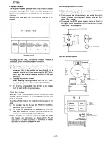
Parts layout
LED VHPGL9EG2/1-1
LDl
CON2 25Pin QCNCW1005EC2E
C3 O.lµF
KATHOD
K
D4
A
---crr::=r-
L1
Jumper wire (cotton sheathed)
0
~
'8C2021,2
~.'.H
It)
Cl
®
TR3 TR2
12V
.
.0::
o
B
B
C2
~
~
104M
10,uF
8
C
C
E
E
R3
8
~
Rl
CfI~1 I
I
~
CQCNCM 1003EC5J
ANODE
A
R
Red
Jl
lSS108
A
K
A (Anode)
~
K (Cathode)
~
(Pattern side)
NOTE:
Slack in the jumper
(J1
I
must be treated
in the
opposite
direction
as the 25·pin
connector,
be-
cause the rib is provided between the connector
and Jl.
Note the notch
E
C
Diode
GL9EG2
The anode must be
installed to the side
A of the board.
Tantalum capacitor
Black/whlte
A
K
A (Anode)
~
K (Cathode)
I
0
)) )
I
Green/blue
1S1588L1
1
~K
K (Cathode)
A (Anode)
-101-
Содержание PC-1600
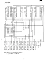
Страница 42: ... 11 CIRCUIT DIAGRAM PARTS POSITION KEY P W B LCD SIDE 39 ...
Страница 43: ...PC l600 40 ...
Страница 44: ...PC 1000 KEY P W B LSI SIDE 41 ...
Страница 45: ... 42 ...
Страница 48: ... PC l600 F P C P W B 45 ...
Страница 49: ... Kn 46 ...
Страница 52: ... PC l600 CONNECTOR P W B 49 ...
Страница 53: ... 50 ...
Страница 55: ... __ PC l600 tli I ONLY Pc 1600K I I 1 I 52 l J ...
Страница 56: ... PC l600 K MEMORY P W B ROM Cut c IJ O lJ1F C O lJ1F I Bend capacitor to inward ROM SIDE 53 ...
Страница 57: ...RAM SIDE 54 ...
Страница 61: ...I I 2 3 4 42 58 ...
Страница 92: ... PC l600 POWER SUPPLY P W B BACK VIEW MAIN P W B I Capacitor l00µF 10V mounting 20 25 tJ WB Oo 89 ...
Страница 93: ... P W B LSI SIDE t 90 ...
Страница 95: ... PC 1600 I rr 25 c oA C Screws are required torque control See service precation on section 6 page 69 93 ...
Страница 117: ... PC I600 ...


