MX-2310U MX-2310U (MAIN UNIT) 2 – 13
6)
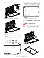
Set the color patch image (adjustment pattern) printed in the
procedure 5) on the document table.
Set the color patch image (adjustment pattern) printed in the
procedure 2) on the document table. Place the color patch
image so that the fine lines are on the left side. At that time,
place 5 sheets of white paper on the printed color patch image
(adjustment pattern).
7)
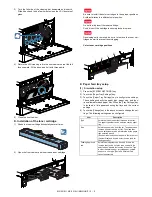
Select [FACTORY] target, and press [EXECUTE] key.
When the color balance is customized with the manual color
balance adjustment (SIM 67-25) according to the user's
request and the color balance is registered as the service tar-
get with SIM 67-27, if the color balance is adjusted to that color
balance, select the [SERVICE] target.
The printer color balance adjustment (step 1) is automatically
performed and the color balance check patch image is printed
out.
If there is any streak or unclear print on the printed check pat-
tern, check the print engine for any problems.
8)
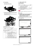
The initial setting menu of the half tone image correction is dis-
played. Press [OK] key.
The initial setting of the half tone image correction is per-
formed.
9)
Wait until [EXECUTE] key is displayed. When it is displayed,
press it.
The half tone image correction is performed.
PRINTER CALIBRATION
ǂǂǂ6,08/$7,21ǂǂ12
&/26(
7(67
(1*,1($872$'-8670(176(59,&(
2.
3/($6(:$,7
12:5(*,67(5,1*7+(1(:7$5*(72)+$/)721(352&2167
PRINTER CALIBRATION
3
1 2
0
/
.
-
,
+
*
)
(
'
&
%
$
#
;
/
%
$M
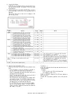
1) The max. density section is not blurred.
2) Patch C or D of each of Y, M, C, and BK is very slightly copied.
3) Patch for each of Y, M, C, BK
The patch density is identical between patches or not reversed.
The patch density is changed gradually.
High density
Low density
ǂǂǂ6,08/$7,21ǂǂ12
&/26(
7(67
(1*,1($872$'-8670(176(59,&(
&21),507+($'-867('3$7&+$1'35(66>2.@725(*,67(57+,63$7&+'$7$
2.

