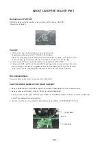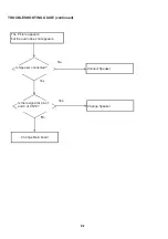
Distinction of PbF PCB:
PCBs (manufactured) using lead free solder will have a PbF printing on the PCB.
(Please refer to figures.)
Caution:
• Pb free solder has a higher melting point than standard solder;
Typically the melting point is 86
o
F~104
o
F(30
o
C~40
o
C) higher.
Please use a soldering iron with temperature control and adjust it to 650
o
F ± 20
o
F (350
o
C ± 10
o
C).
In case of using high temperature soldering iron, please be careful not to heat too long.
• Pb free solder will tend to splash when heated too high (about 1100
o
F/ 600
o
C).
• All products with the printed circuit board with PbF printing must be serviced with lead free solder.
All products with the printed circuit board with PbF printing must be serviced with lead free solder.
When soldering or unsoldering, completely remove all of the solder from the pins or solder area,
and be sure to heat the soldering points with the lead free solder until it melts sufficiently.
Recommendations
Recommended lead free solder composition is Sn-3.0Ag-0.5Cu.
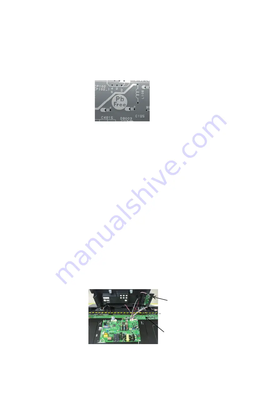
1. Remove SCREWs from COVER BACK ASS'Y and hold the COVER BACK ASS'Y as the below Picture.
2. Remove connector of CD2201
䇮
CD2202
䇮
CD301 from MAIN PCB BOARD.
In doing so, take care the space NOT to touch T-CON PCB , COVER BACK ASS'Y must be held off the T-CON PCB
( as NOT over dashed line in below picture).
3. And then, also take care for cables NOT to be fallen down from RIBs on COVER BACK ASS'Y side.
COVER BACK
T-CON PCB
SPACE
CAUTION WHEN REMOVE THE REAR CABINET
A1-2
ABOUT LEAD FREE SOLDER (PbF)
Содержание LC-23LE448RU
Страница 32: ...㪰 I 1 WAVEFORMS ...


