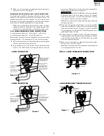

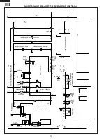
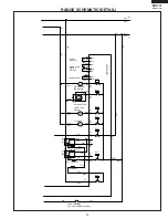
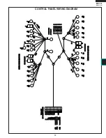

19
KB-3411JS
KB-3411JK
KB-3411JW
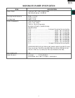
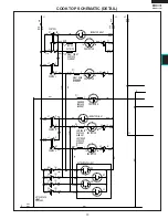
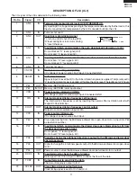
Pin No.
Signal
I/O
Description
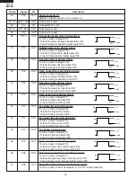
the signals holds “H” level during microwave cook-
ing and “L” level while not cooking. In other cook-
ing modes (90%, 80%, 70%, 60%, 50%, 40%,
30%, 20%, 10%, 0%) the signal turns to “H” level
and “L” level in repetition according to the power
level.
48-52
P04-P00
OUT
Used for initial balancing of the bridge circuit (absolute humidity sensor).
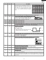
53
P57
OUT
Common relays driving signal. (Square Waveform : 60Hz)
To turn on and off the shut-off relays (RY1 and
RY3). The square waveform voltage is delivered
to the relays (RY1 and RY3) driving circuit.
54
P56
IN
Signal coming from key unit.
55
TXD1
IN
Signal coming from key unit.
56
RXD1
IN
Signal coming from key unit.
57
P53
IN
To input signal which communicates the oven door open/close information to LSI.
Door open "H" level signal (+5V). Door close "L" level signal (GND).
58
P52
OUT
Signal to sound buzzer.
A: Key touch sound.
B: Completion sound.
C: When the oven stops so that the food can be
checked in Automatic cooking mode.
59
P51
IN
Input signal which communicates the drawer door open/ close information to LSI.
Door opened; “H” level 5V).
Door closed; “L” level signal(0V).
60
INT0
IN
Signal to synchronize LSI with commercial power source frequency.
This is the basic timing for all real time processing of LSI.
61
AVSS
IN
A/D converter power source voltage.
The power source voltage to drive the A/D converter in the LSI.
62
VREF
IN
Reference voltage input terminal.
A reference voltage applied to the A/D converter in the LSI. Connected to +5V.
63
AN7
IN
AH sensor input.
This input is an analog input terminal from the AH sensor circuit, and connected to the A/
D converter built into the LSI.
64
AN6
IN
Used for initial balancing of the bridge circuit (absolute humidity sensor). This input is an
analog input terminal from the AH sensor circuit, and connected to the A/D converter built
into the LSI.
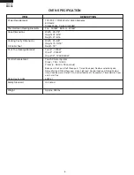
Microwave cooking mode
Other cooking mode
VARI MODE
ON TIME OFF TIME ON TIME OFF TIME
100% power
32 sec.
0 sec.
60sec.
0ec.
90% power
30 sec.
2 sec.
54sec.
6sec.
80% power
26 sec.
6 sec.
48sec.
12sec.
70% power
24 sec.
8 sec.
42sec.
18sec.
60% power
22 sec.
10 sec.
36sec.
24sec.
50% power
18 sec.
14 sec.
30sec.
30sec.
40% power
16 sec.
16 sec.
24sec.
36sec.
30% power
12 sec.
20 sec.
18sec.
42sec.
20% power
8 sec.
24 sec.
12sec.
48sec.
10% power
6 sec.
26 sec.
4sec.
56sec.
0% power
0 sec.
32 sec.
0sec.
60sec.
During cooking
L: GND
H: +5V
16.7 msec.
A
B
C
H: +5V
L: GND
0.1 sec
2.0 sec
1.0 sec
1.0 sec
16.7 msec.
H : +5V
L : GND
Содержание KB-3411JK
Страница 6: ...4 KB 3411JS KB 3411JK KB 3411JW NOTES ...
Страница 13: ...11 KB 3411JS KB 3411JK KB 3411JW KB 3411JW ...
Страница 59: ...57 KB 3411JS KB 3411JK KB 3411JW NOTES ...


