background image

11

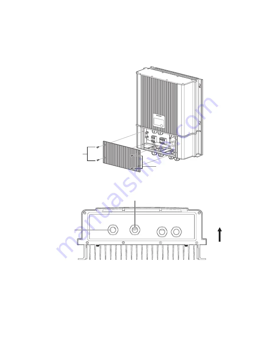
Removing the Front Panel

Remove the front panel of the solar power inverter.

(1) Remove the 4 screws from the lower part of the front panel of the solar power inverter. 

Then remove the front panel.

(2) The four glands shown below should be used for the purpose indicated. If there are any 

unused or open glands, they should be covered.

Screws

Screws

(Front)

DC Disconnect
(PV Strings)

AC Disconnect

Содержание JH-1600E

Страница 1: ... Mount the Solar Power Inverter 7 Wiring Solar Power Inverter 9 Before wiring 10 Removing the Front Panel 11 Solar Power Inverter Wiring Overview 12 Connecting to DC Disconnect 13 Connecting to AC Disconnect 15 Test Run 18 Checking the PV Array DC Voltage 18 Checking the AC Utility Voltage 18 Starting Up the Inverter 18 Monitoring the Inverter 19 Display Panel 19 Status Indicator Lights 19 Monitor...

Страница 2: ...or injuries caused by or resulting from causes not attributed to faulty parts in the manufacture of the product including but not limited to defect or injury caused by or resulting from misuse abuse neglect accidental damage improper voltage incorrect system design vermin infestation storm damage fire flood exposed to corrosive conditions or any alterations made to the product which are not author...

Страница 3: ...the manufacturer will not liable for any claims Correct installation will assist the maximum amount of electricity to be exported to the grid To avoid electric shock or burns always follow all warnings and cautions marked on the solar power inverter and in this manual Ensure that all electrical connections are secure loose connections can cause overheating smoke and fire This solar power inverter ...

Страница 4: ...omatically controls the operation of the system Watt hour Meter AC Meter Grid 5 Solar Power Inverter 1 2 4 6 PV String Introduction Outline of Grid Interactive Home PV System The home PV system is a grid connected type product that includes the following components PV modules that convert light into DC electricity a solar power inverter that changes DC electricity into AC and blends the power with...

Страница 5: ...3 Dimensions Solar Power Inverter 408 440 5 348 141 Unit mm ...

Страница 6: ...he carton box Bracket 1 piece Installation operation manual 1 manual Inspection report 1 report Screws for the solar power inverter 2 pieces 6 32 UNC 10 Screws for the bracket 10 pieces 5 5 1 8 80 60 60 60 60 180 60 60 60 60 330 347 EXTRUDE M5xP0 8 4PL 199 5 330 174 5 40 5 174 5 405 6 25 25 12 293 303 287 52 47 Unit mm ...

Страница 7: ...IONS section on page 1 For best performance the inverter should be installed in a cool shady area Do not install the solar power inverter in a location Higher than the altitude of about 2 000 m above sea level Close to corrosive gas or liquid Near salt water Exposed to direct sunlight Prone to flooding or high levels of snow pack Minimal or no air flow high humidity or condensation Near television...

Страница 8: ...he wall as required for a secure installation Make sure that ventilation of the solar power inverter is unobstructed Keep the clearance on the upper of the solar power inverter more than 300 mm the lower more than 500 mm and the left and right sides more than 150 mm each Make sure that the lower side of the solar power inverter has 1500 mm and the front side has 700 mm clearance for the electricia...

Страница 9: ...nt Bracket Dimensions The dimensions of the mounting bracket are shown in figure below 1 Use 10 pcs screws 5 5 1 8 80 to fix the mounting bracket 2 Seal the space between the bracket and the wall with cauking as shown the picture below 60 120 60 180 60 120 60 196 134 40 5 Unit mm Wall Sealing Sealing Sealing ...

Страница 10: ...bracket Key holes located on the upper side and middle side of the inverter unit are for hanging the unit on the bracket place key holes on the 4 hexa bolt head the bracket 4 Use 2 pcs screws to fix the JH 1600E on the mounting bracket Front ...

Страница 11: ...on the AC meter The DC disconnect switch The AC disconnect switch Do not turn on the DC and AC disconnect switch until the wiring installation is finished Unused cable opening must be covered Grounding installation is the responsibility of the installer To avoid the risk of fire or electrical shock use proper sized wires To reduce the risk of short circuits during installation or servicing of the ...

Страница 12: ...ervice panel to inverter 1 Connect the ground wire green and yellow from the ground terminal in the main utility service panel to GND terminal in the inverter 2 Connect the L or Line to Line terminal in the inverter 3 Connect the N or Neutral to Neutral terminal in the inverter 4 Ensure all connections are correctly wired and proper torque according to values shown in the table below DC cables iso...

Страница 13: ... screws from the lower part of the front panel of the solar power inverter Then remove the front panel 2 The four glands shown below should be used for the purpose indicated If there are any unused or open glands they should be covered Screws Screws Front DC Disconnect PV Strings AC Disconnect ...

Страница 14: ... inverter 4 Making the AC connections from inverter to main utility service panel WARNING FIRE SHOCK AND ENERGY HAZARD Before wiring the inverter read all instructions and cautionary markings located in this manual on the PV array and on the main service panel CAUTION Note the polarity of PV cable Black wire Positive White wire Negative Solar Array SHARP Solar Power Inverter Utility Grid GROUND Ne...

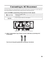
Страница 15: ... CAUTION of Wiring Solar Power Inverter page 9 1 Install two copper wires positive and negative from the DC disconnect through the conduit 2 Attach a forked spade or lug connector to the cables before connecting to the terminal block Pass the wire through the gland before connecting to the terminal Make sure DC disconnect is open DC terminal block for DC disconnect ...

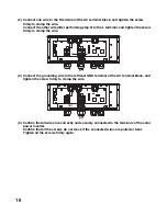
Страница 16: ...les before connecting to the terminal block 5 Connect the white wire to the negative terminal of the terminal block and tighten the screw firmly to clamp the wire 6 Confirm all of the wires are correctly and securely connected to the terminals of the solar power inverter WARNING SHOCK HAZARD The inverter must be grounded by connection to a grounded permanent wiring system ...

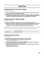
Страница 17: ...NG and CAUTION of Wiring Solar Power Inverter page 9 1 Attach a forked spade or lug connector to the AC cables before connecting to the terminal block Pass the wire through the gland before connecting to the terminal Make sure AC disconnect is open Use outdoor wiring and conduit on the outdoor section between the solar power inverter and the PV modules The AC disconnect includes over current prote...

Страница 18: ... screw firmly to clamp the wire 3 Connect the grounding wire to the leftmost GND terminal of the AC terminal block and tighten the screw firmly to clamp the wire 4 Confirm that all wires are correctly and securely connected to the terminals of the solar power inverter Confirm that all the screws do not move if the connected wires are pulled or bent Tighten all the screws firmly again N L GND ...

Страница 19: ...neutral voltage range around the nominal value See Output section in Electrical Specification page 23 for the utility voltage operating range for your inverter model After performing the voltage checks reattaching all covers that were removed during installation and startup Starting Up the Inverter To start up the inverter 1 Switch the AC disconnection switch breaker to the ON position 2 Switch th...

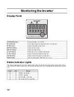
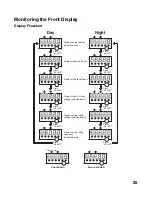
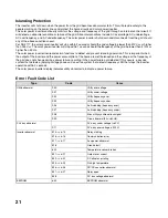
Страница 20: ...ault Code list W LED Yellow Displays instantaneous power watts Wh D LED Yellow Displays watt hours today kWh LED Yellow Displays total kilowatt hours VDC LED Yellow Displays input PV array voltage instantaneously VAC LED Yellow Displays output utility voltage instantaneously Hz LED Yellow Displays output utility frequency instantaneously SELECT button Press to cycle through W Wh D kWh VDC VAC Hz G...

Страница 21: ...watt hour Displays input PV array voltage instantaneously Displays output utility voltage instantaneously Displays output utility frequency instantaneously Day Press SELECT Press SELECT Press SELECT Press SELECT Press SELECT Press SELECT Press SELECT Press SELECT Press SELECT Press SELECT Press SELECT Night Flash 1 Hz Count down Error occurred ...

Страница 22: ...utput of the inverter and the power consumption of the home are well balanced and the voltage or the frequency of the grid does not change during a power failure resulting in the power failure not detected If this occurs a passive system that detects a jumping voltage phase and an active system that detects frequency shift that stops the inverter operation within 2 seconds The solar power inverter...

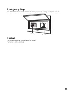
Страница 23: ... AC disconnect and the DC disconnect when you execute an emergency stop of the inverter Restart Turn on the AC disconnect first and then DC disconnect The inverter restarts automatically Turn off Turn off DC disconnect AC disconnect ...

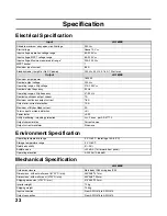
Страница 24: ...us output current 7 A Maximum continuous output current 7 6 A Output over current protection 10 A Maximum utility backfeed current 0 A Total current harmonic distortion 5 Power factor 0 99 Utility monitoring islanding protection VAC Fac as per AS 4777 2 Output characteristics Current source Output current waveform Sine wave Operating temperature range 20 C 60 C derating at 40 60 C Storage temperat...

Страница 25: ...e Sec 6 1 0 1 4 1 8 Protection timer Sec 7 10 60 150 300 Option This setting is not used Do not change the parameter Leave the value as default of 5 8 5 One thing at a time 31 Operating frequency Sec 9 50 60 Press ENT for 5 seconds Normal operation ENT SEL ENT SEL Press SEL ENT SEL Press SEL ENT SEL The output power goes back one day as SEL is pressed The display returns to the current day by pres...

Страница 26: ...26 Memo ...

Страница 27: ...TiNSJ0546SNZZ 1 Huntingwood Drive Huntingwood NSW 2148 by phone on 1300 135 022 or by fax on 1300 727 717 WEB site http www sharp net au ...

Отзывы: