UX-470ES/SE/AT
FO-880ES/AT
2 – 12
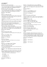
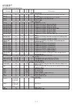
• Soft switch function description
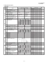
SW-A1 No. 1 Protect from echo
Used to protect from echo in reception.
SW-A1 No. 2 Forced 4800BPS reception
When line conditions warrant that receptions take place at 4800 BPS
repeatedly.
It may improve the success of receptions by setting at 4800BPS.
This improves the receiving document quality and reduces handshake
time due to fallback during training.
SW-A1 No. 3 Footer print
When set to "1", the date of reception, the sender machine No., and the
page No. are automatically recorded at the end of reception.
SW-A1 No. 4 Length limitation of copy/send/receive
Used to set the maximum page length.
To avoid possible paper jam, the page length is normally limited to 0.6
meter for copy or transmit, and 1 meters for receive.
It is possible to set it to "No limit" to transmit a long document, such as a
computer print form, etc. (In this case, the receiver must also be set to
no limit.)
SW-A1 No. 5 CSI transmission
(CSI TRANSMISSION) is a switch to set whether the machine sends or
does not send the signal (CSI signal) informing its own telephone No. to
the remote fax machine when information is received. When "nonsending"
is set, the telephone No. is not output on the remote transmitting ma-
chine if the remote transmitting machine has the function to display or
print the telephone No. of receiving machine, using this CSI signal.
SW-A1 No. 6 DIS receive acknowledgment during G3 transmission
Used to make a choice of whether reception of DIS (NSF) is acknowl-
edged after receiving two DISs (NSFs) or receiving one DIS (two NSFs).
It may be useful for overseas communication to avoid an echo sup-
pression problem, if set to 1.
SW-A1 No. 7 Non-modulated carrier for V29 transmission modem
Though transmission of a non-modulated carrier is not required for trans-
mission by the V29 modem according to the CCITT recommendation, it
may be permitted to a send non-modulated carrier before the image
signal to avoid and echo suppression problem. It may be useful for over-
seas communication to avoid an echo suppression problem, if set to 1.
SW-A1 No. 8 EOL (End Of Line) detect timer
Used to make a choice of whether to use the 25-seconds or 5-seconds
(ES)/ 13-seconds(SE/AT) timer for detection of EOL.
This is effective to override communication failures with some facsimile
models that have longer EOL detection.
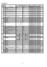
SW-A2 No. 1 ~ No. 4 Modem speed
Used to set determine the initial modem speed. The default is 9600BPS.
It may be necessary to program it to a slower speed when frequent line
fallback is encountered, in order to save the time required for fallback
procedure.
SW-A2 No. 5 Sender’s information transmit
(SENDER’S INFORMATION TRANSMISSION) is a switch to set the
function to print the content of HEADER PRINT described in the passcode
list at the front end of receiver’s original when original is sent to the
remote machine.
If this switch is set to "NO", the HEADER PRINT is not output at the
receiving machine.
SW-A2 No. 6 H2 mode
Used to determine reception of H2 mode (15 sec transmission mode).
When set to OFF, H2 mode reception is inhibited even though the
transmitting machine has H2 mode function.
SW-A2 No. 7 Communication error treatment in RTN sending mode
(Reception)
Used to determine communication error treatment when RTN is sent by
occurrence of a received image error in G3 reception. When it is set to
"1", communication error is judged as no error.
SW-A2 No. 8 CNG transmission
When set to "0" , this model allows CNG transmission by pressing the
Start key in the key pad dialing mode. When set to "1", CNG transmis-
sion in the key pad dialing mode cannot be performed. In either case,
CNG transmission can be performed in the auto dial mode.
SW-A3 No. 1, No. 2 CED tone signal interval
For international communication, the 2100Hz CED tone may act as an
echo suppression switch, causing a communication problem.
Though SW-A3 No. 1 and No. 2 are normally set to 0, it should be changed
this time between the CED tone signal to eliminate the communication
problem caused by echo.
SW-A3 No. 3 MR Coding
Used to select the MR coding enable or disable.
SW-A3 No. 4 ~ No. 8 Reserved
Set to "0".
SW-A4 No. 1 ~ No. 5 Signal transmission level
Used to control the signal transmission level in the range of-0dB to-
31dB.
The factory setting is at -11dB (MODEM output).
SW-A4 No. 6 Protocol monitor (Error print)
If set to "1", protocol is printed at communication error.
SW-A4 No. 7 Protocol monitor
Normally set to "0". If set to "1", communication can be checked, in case
of trouble, without using a G3 tester or other tools.
When communication FSK data transmission or reception is made, the
data is taken into the buffer. When communication is finished, the data
is analyzed and printed out. When data is received with the line monitor
(SW-A4 No. 8) set to "1" the reception level is also printed out.
SW-A4 No. 8 Line monitor
Normally set to "0". If set to "1", the transmission speed and the recep-
tion level are displayed on the LCD. Used for line tests.
SW-A5 No. 1, No. 2 Digital line equalization setting (Reception)
Line equalization when reception is to be set according to the line char-
acteristics.
Setting should be made according to distance between the telephone
and the telephone company central switching station.
SW-A5 No. 3, No. 4 Reserved
Set to "0".
SW-A5 No. 5, No. 6 Digital cable equalizer setting
(Reception for Caller ID) (SE only)
Line equalization when reception for CALLER ID is to be set according
to the line characteristics.
Setting should be made according to distance between the telephone
and the telephone company central switching station.
SW-A5 No. 7 Error criterion
Used to select error criterion for sending back RTN when receiving im-
age data.
SW-A5 No. 8 Anti junk fax check
When using the Anti junk fax function, set to "1".
TX
RX
CED
DIS
T
Содержание FO-880
Страница 6: ...1 4 UX 470ES SE AT FO 880ES AT M E M O 1 11 ...
Страница 25: ...UX 470ES SE AT FO 880ES AT 2 19 M E M O ...
Страница 46: ...UX 470ES SE AT FO 880ES AT Control PWB parts layout Top side 6 7 ...
Страница 47: ...UX 470ES SE AT FO 880ES AT Control PWB parts layout Bottom side 6 8 ...
Страница 54: ...UX 470ES SE AT FO 880ES AT TEL LIU PWB parts layout Top side 6 15 ...
Страница 55: ...UX 470ES SE AT FO 880ES AT TEL LIU PWB parts layout Bottom side 6 16 ...
Страница 57: ...UX 470ES SE AT FO 880ES AT Power supply PWB parts layout 6 18 ...

