ER-A520/A530
– 6 –
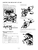
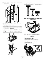
8) Install the attached pole cabinet
G
to the pole cabinet
7
to fix it
with the screw
H
.
9) Install the pole cabinet
G
in the opposite order of the disassembly.
10) Fastening on the table:
Secure the Base cabinet
2
using the screw.
Lowering the height of the UP-P16DP
Remove the standard Pole and attach the Base cabinet to the Ratch .
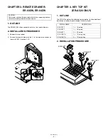
CHAPTER 6. EXPANSION RAM BOARD
(UP-S02MB)
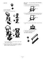
CHAPTER 7. DRAWER POSITION
CHANGE
1) Remove the cabinet fixing screw
1
.
2) Slide the cabinet to the left, and remove the cabinet.
3) Insert the pawl of the cabinet into the hole
A
at the back.
4) Slide the cabinet to the right.
5) Tighten the cabinet fixing screw
1
.
No.
NAME
USE
Q’ty
I
Screw (M4 x 16)
S e c u r i n g t h e U P - P 1 6 D P t o t h e
wooden table
4
J
Screw (M4 x 20)
Securing the UP-P16DP to the metal
table
4
K
Nut
Securing the UP-P16DP to the metal
table
4
Display cable
7
7
11
11
12
12
13
13
14
14
15
15
memory board
main board
A
1


