background image

Содержание ER-A460

Страница 1: ... WALL OUTLET CHAPTER 1 SPECIFICATIONS 1 CHAPTER 2 OPTIONS 6 CHAPTER 3 SRV RESET AND MASTER RESET 9 CHAPTER 4 HARDWARE DESCRIPTION 10 CHAPTER 5 TEST FUNCTION 32 CHAPTER 6 DOWN LOAD FUNCTION 39 CHAPTER 7 CIRCUIT DIAGRAM PWB LAYOUT 41 PARTS GUIDE CONTENTS SHARP CORPORATION This document has been published to be used for after sales service only The contents are subject to change without notice Parts ...

Страница 2: ...tch Infrared sensor Keyboard Drawer Ribbon cover Receipt paper Printer cover Journal window Drawer lock To lock or unlock the drawer use the drawer lock key Power switch Velidation opening To lock or unlock the printer cover use the printer cover lock key Printer cover lock Customer display Pop up type Operator display Mode switch Infrared sensor Keyboard Drawer Ribbon cover Receipt paper Printer ...

Страница 3: ...13 GC COPY RF RA PO VAT NS 6 12 18 10 ST EX1 EX2 3 6 9 12 8 16 24 2 5 8 11 7 15 23 1 4 7 10 6 14 22 5 13 21 4 12 20 3 11 19 2 10 18 1 9 17 RCPT VP CASH VAT GC COPY CL 0 00 000 1 2 3 4 5 6 7 8 9 RF PO 1 2 RA 1 2 AMT PLU SUB AUTO NS ST L3 L2 L1 CR2 CR1 CH EX1 TL 32 31 30 29 28 27 26 25 40 39 38 37 36 35 34 33 48 47 46 45 44 43 42 41 56 55 54 53 52 51 50 49 64 63 62 61 60 59 58 57 RECEIPT JOURNAL 2 ...

Страница 4: ...ey CH1 Cheque 1 key CH2 Cheque 2 key CH Cheque key AMT Amount key ST Subtotal key TL Total cash total key L1 PLU s level shift 1 key L2 PLU s level shift 2 key L3 PLU s level shift 3 key 2 Option key top KEY TOP DESCRIPTION ER A460 ER A470 L1 PLU s level shift 1 key L2 PLU s level shift 2 key L3 PLU s level shift 3 key DEPT 19 50 Department 19 50 keys DEPT 13 50 Department 13 50 keys PLU 1 82 Dire...

Страница 5: ...amp lights up when PLU level is 3 CHR The lamp lights up when character key sheet mode in text setting SML The lamp lights up when small characters are being inputted in text setting DC The lamp lights up when double width characters are being inputted in text setting ONL The lamp lights up when the machine is connected to the online transmission line and it goes off when the machine is disconnect...

Страница 6: ... 4 Inking Ink supply system Ink ribbon Form Cartridge Endless ribbon Specification Material Nylon Ribbon life Approx 6 million characters Print color Purple single color 5 Logo stamp Material Porous rubber Stamp color Purple single color Max stamp size 30 W 20 H mm Ink refill Allowed UINK 1001CCZZ 5CC 6 Cutter Method Manual 6 Drawer 1 Specification 1 Drawer box and drawer Model name of the drawer ...

Страница 7: ...OMPUTER LOCAL PURCHASE OPTION RAM ER 01RA 02RA TEXT PRESET REMOTE KEY ER 01RK ER A5RS RS 232C I F MAX 2 PORTS ER A460 A470 MASTER MACHINE IR comunication ER A46R1 OPTION CONT ROM SERVICE OPTION ER A5CL REMOTE DRAWER DRAWER COIN CASE COIN CASE COVER ER 48CC3 ER 02CV1 5 WIRELESS INTERFACE CABLE CE IR2 IR4 IR comunication 3 5 inch FDD ER 01 02FD COMMERCIAL PRODUCT 1 HOLE CASHIER SW Fig 1 1 6 ...

Страница 8: ...OVER G C O V B 7 1 0 8 B H Z Z BA 3 MODE KEY GRIP COVER L K G I M 7 1 2 6 R C Z Z AL OP key only 4 DRIP PROOF KEYBOARD COVER G C O V B 7 1 0 9 B H Z Z BF 5 JOURNAL NEAR END SENSOR D U N T 4 9 4 5 B H Z Z AY 6 PROGRAMMING CHARACTER KEYBOARD COVER G C O V B 7 1 1 0 B H Z A BE 7 REMOTE DRAWER C B O X D 7 1 3 6 B H 0 1 BU 8 CLERK COVER B G C O V A 7 1 0 7 B H Z B AG For ER A5CL CLERK ANGLE L A N G T 7...

Страница 9: ...ide connect the I F PWB to OPTCN2 To check from the parts side connect to OPTCN3 Note The option I F PWB should be held horizontally so that no excessive stress is applied to connecting section A in Fig 7 2 Procedure 2 Fig 7 3 Put a string between the pop up and the option PWB as shown in Fig 7 3 Adjust the length of the string so that the CKOG 6708RCZZ and the option PWB are not binding Then perf...

Страница 10: ... SRV position MRS 2 Used to clear all memory and keyboard contents This reset returns all programming back to defaults The keyboard must be entered by hand This reset is used if an application needs different keyboard layout other than that supplied by a normal MRS 1 Procedure 1 Unplug the AC cord from the wall outlet 2 Set the MODE switch to the SRV position 3 Plug in the AC cord to the wall outl...

Страница 11: ...INTER DP 730 STANDARD RAM1 32KB OPTIONAL RAM2 MAX 128KB ER 01RA 32KB ER 02RA 128KB STANDARD ROM 256KB OPTIONAL ROM 128KB ER A46R1 SWITCH KEY BOARD RS232 I F 2 ports ER A5RS OPT CN CKDC6 1 LINE 7SEG 7DIG 2 LINE 5 x 7DOT 12DIG 5 x 7SEG 10DIG CUSTOMER DISPLAY OPERATER DISPLAY I R UNIT ER 01RK Other ECR 10 ...

Страница 12: ... IRQ2 IRQ1 IRQ0 VCC AVCC P73 AN3 112 111 110 109 108 107 106 105 104 103 102 101 100 99 98 97 96 95 94 93 92 91 90 89 88 87 86 85 TMCI P42 P43 FTI1 P45 FTI2 P47 VSS P50 FTCA1 P51 P52 P53 P54 FMRS P56 P57 STOP P60 ER P61 DR P62 CS P63 CD P64 RR P65 RS P66 P67 VSS AVSS AN0 AN1 57 58 59 60 61 62 63 64 65 66 67 68 69 70 71 72 73 74 75 76 77 78 78 80 81 82 83 84 A8 A9 A10 A11 A12 A13 A14 A15 VSS A16 A1...

Страница 13: ... D7 D6 D5 D4 D3 D2 D1 D0 D15 D14 D13 D12 D11 D10 D9 D8 STOP P57 P56 FMRS P54 P53 P52 P51 P50 P67 P66 RS P65 RR P64 CD P63 CS P62 DR P61 ER P60 P73 AN2 AN1 AN0 TXD2 RXD2 TXD1 RXD1 SCK2 IRQ2 IRQ1 IRQ0 H8 500 CPU DTC Serial communication interface x 2ch 8bit timer 16bit free running timer x 2ch Refresh controller Wait state controller A D convertor Interruption controller Clock oscillator Watch dog t...

Страница 14: ...mote drawer No 2 open signal NU 54 P37 DR3 Out Remote drawer No 3 open signal NU GND 55 VCC VCC In 5V 56 P40 IFV In Slip printer M 240 interface connect signal NU 57 TMCi PTMG In Printer DP 730 timing signal 58 P42 TOF In Slip printer M 240 TOF sensor signal NU 59 P43 BOF In Slip printer M 240 BOF sensor signal NU 60 FTi1 PRST In Printer DP 730 reset signal 61 P45 NEJ In Near end sensor journal si...

Страница 15: ... Crystal oscillator connection 99 XTAL XTAL In Crystal oscillator connection 100 VSS NU In GND 101 X X Out System clock 102 E NU Out Nu 103 AS AS Out Address strobe 104 RD RD Out Read 105 HWR WR Out Write 106 LWR LWR Out Nu 107 RFSH RFSH Out Refresh cycle 108 VCC VCC In 5V 109 MD0 MD0 In 5V MODE 3 110 MD1 MD1 In 5V MODE 3 111 MD2 MD2 In GND MODE 3 112 STBY STBY In 5V Nu 14 ...

Страница 16: ...U 137 RJMTD 136 RJMTS 135 DT5 134 DT6 133 DT7 132 GND 131 DT1 130 DT2 129 DT3 128 DT4 127 RJTMG 126 RJRST 125 RAS1 124 RAS2 123 ROS2 122 ROS1 121 OPTCS 41 D3 42 GND 43 D4 44 D5 45 D6 46 D7 47 SSPRQ 48 RESET 49 INT2 50 INT3 51 RXDI 52 TXDI 53 SCKI 54 IRQ0 55 A0 56 A1 57 A2 58 A3 59 A4 60 A5 61 GND 62 VCC 63 A6 64 A7 65 A8 66 A9 67 A10 68 A11 69 A12 70 A13 71 A14 72 A15 73 A16 74 A17 75 A18 76 A19 7...

Страница 17: ...XINT2 EXINT3 SDT1 7 DT1 9 TEST IRQ0 A23 A0 SSPRQ SLF SLRS VF RF JF FCUT PCUT STAMP TRGI TRG TRG DOTEN IRLON D0 D7 Φ Address decode External CS Internal CS RASEL Image control SSP comparison register BAR Buffer Read write control Divider CHS serial select Multiplexer WAIT control CAPS select Print gate Print pulse control Print mode PMD INTO control Printer control port Motor drive Output selection...

Страница 18: ... I O Data bus 2 41 D3 I O Data bus 3 42 GND GND 43 D4 I 0 Data bus 4 44 D5 I 0 Data bus 5 45 D6 I 0 Data bus 6 46 D7 I 0 Data bus 7 47 SPRQ Out SSP interrupt request to CPU 48 RESET In MPCA reset 49 INT2 In Interrupt signal Nu Pin No Signal name In Out Function 50 INT3 In Interrupt signal Nu 51 RXD2 Out 8 bit serial port output to CPU 52 TXD2 In 8 bit serial port input from CPU 53 SCK2 In Serial p...

Страница 19: ...ter motor lock detection signal NU 147 SLMTD In Nu 148 SLMTS In Nu 149 SLMTR In GND 150 HTS2 Out Nu 151 SCK2 Out Nu 152 STH2 In Nu 153 Nu 154 Nu 155 Nu 156 Nu 157 Nu 158 LCDWT Nu 159 DOTEN Out Dot drive enable signal 160 RASP Nu 2 3 CKDC6 HD404728A91FS 1 General description The CKDC6 is a 4 bit microcomputer developed for the ER A460 A470 and provides functions to control the real time clock keys ...

Страница 20: ...ET PULL DOWN Pin No Port I O RESET State Signal name I O Notes PULL UP DOWN 34 R73 S02 I O O DS0 O DOT DISP CONT SO 35 R80 I O O SHEN O SHEN 36 R81 I O O KRQ O KEY REQUEST 37 R90 I I KR0 I KEY RETURN 0 38 R91 I I KR1 I KEY RETURN 1 39 R92 I I KR2 I KEY RETURN 2 40 R93 I I KR3 I KEY RETURN 3 41 RESET I I CKDCR I CKDC IV RESET 42 OSC2 4 19 MHz X tal 43 OSC1 44 GND GND 45 CL1 32 768 KHz OSC 46 CL2 47...

Страница 21: ... prepare for the power off situation The signal STOP is supplied to the CKDC6 as signal RESET to reset the devices This circuit monitors 24V supply voltage The voltage at the pin of the comparator GL393 is always main tained to 5 1V by means of the zener diode ZD5 while 24V supply voltage is divided through the resistors R19 R20 and R21 and is applied to the pin When normal 24V is in supply 6 8V i...

Страница 22: ...C07FFFH This area is identical to IPL ROM area which will beseparately developed RAM image area Image is formed in RAM area address 1D8000H1DFE7FH Note Note Image can be formed in lower 32KB of RAS2 3 ROM area memory map Fig 5 3 These two decode signals decode 512KB space respectively and canbe used with max 4MB ROM Note The lower 32KB of ROS1 signal is formed as OR of image area in 0page Internal...

Страница 23: ...rmed with two ROM chip select signals ROS1 and ROS2 which decode 512KB address area respectively to accessmax 4MB ROM 2 RAM control Fig 5 8 Access is performed with two RAM chip select signals RAS1 RAS2 and RAS3 The control register in MPCA6 allows selection of pageimage memory area RAS1 is selected for initializing For 0 page image area selection between RAS1 and RAS2 can bemade with the control ...

Страница 24: ...NMI signal at a synchronized timing and togo to NMI exception process In the exception process routine service routine the entry address is checked to go to SSP sub routine Entry to the break address register BAR is performed through ad dress FFFF00H or later decoded in MPCA6 2 SSP register The break address register BAR is accessed through direct address of FFFF00H FFFFFFH Entry number is 32 entr...

Страница 25: ...control method Access to the enable register and the brake address register is only possible when writing to them from the CPU Information on which brake register the SSP brake is detected in is read as binary data by reading address FFFFFFH 1 Used in an expanded register Normally is a reserve bit Whenreading fixed to 0 If there are 32 break registers binary expression is made with the above 5 bit...

Страница 26: ...eference position of the HP signal The rear edge of RP OFF ON is used as the signal 2 HP signal The pulse signal is outputted from the slit in the disk installed to the DC motor shaft It is used as the reference signal for starting counting of the DP signal It is generated once for twenty DP signals The rear edge of the HP signal ON OFF immediately after generation of the RP signal is used as the ...

Страница 27: ...id may be shorted Be sure to check the head impedance and driver breakdown When fuse F2 is blown 1 Remove F2 and perform the service resetting The set the mode switch to a position other than SRV and SRV and turn off the power 2 Install fuse F2 1 5A and turn on the power If the fuse blows with the above operation driver STA401A may be shorted 3 Turn off the power 4 Disconnect the printer cable fro...

Страница 28: ...es displays timer calendar and buzzer are con trolled by the CKDC 4 on the display PWB Block diagram Fig 9 1 DR0 DRAW0 52 50 DOSP C86 1000P R74 1K TD62308F R73 4 7K 51 DR1 DRAW1 VRESC CPU 24V Drawer solenoid 24V R72 47K IRQ SHEN STH HTS SCK POFF STOP SRES CKDCR HOST SYSTEM 7SEG DISPLAY 10DIG DOT DISPLAY 12DIG G1 G10 SA SG P0 1 4 CKDC 6 P2 3 DIG00 DIG11 POT00 POT35 DOT DISP CONT M66004FP SRES DCS D...

Страница 29: ...r power off after which the STOP output is set low I When STOP goes low the CKDC6 sets RESET low to reset the whole system J And the 5V supply is held at 4 75V or higher voltage after which the voltage drops to a level that the logic circuit does not operate 2 Key and switch scanning Strobes ST0 ST3 are decoded on the keyboard by two 74LS138 3 to 8 decoders to generate 16 strobe signals of S15 S0 ...

Страница 30: ...ter solenoid power 5V VCC Logic power VBAT Battery charge 32V Display tube power VF1 VF2 Display tube power AC VRAM Battery back uped power VCKDC CKDC 4 Back up power 11 Switching regulator circuit Fig 11 1 By switching VIN 28 8V by the transistor TR1 within the STR2024 DC 24V supply is obtained through the LC network Stable 24V is obtained by controlling on off duty of TR1 ION Current when TR1 is...

Страница 31: ... infra red rays are amplitude modulated Secondary modulation With the sub carrier waveform which was modulated in the primary modulation infra red rays are amplitude modulated Modulated waveform Baud rate 2 4 115 2 kbps 9 6 57 6 kbps ZR 5000 9600 bps Serial communication system Start stop synchronization system Data length 8bit Parity None Stop bit 1 Start stop synchronization system Data length 8...

Страница 32: ... IRTX signal from the MPCA6 Q2 is turned on off to light LED1 2 To strengthen the light intensity two LED s are used PD Amplifier Band pass filter Hysteresis comparator ASK AGC Amplifier Bypass filter Hysteresis comparator IRDA REMOCON 5V R67 R70 IC1A R69 C49 C61 R51 R52 R53 IRDA REMOCON MPCA6 C45 Q2 R54 R55 R68 PD1 R56 MPCA6 R56 PD1 R56 R57 C46 R58 R68 R59 Q2 C47 R60 C48 R62 R61 C49 R66 R64 R63 R...

Страница 33: ...118 I F interface test transmission side 120 Standard RAM test 130 Standard ROM test 150 R J printer dot pulse width adjustment 200 Option RAM chip test 400 Option ROM chip test 1 Validation sensor is not used 1 Display test 1 1 Key operation 100 TL 2 Functional description The following is displayed Front display Operator display 3 Check the following items a Check for proper activation of displa...

Страница 34: ...78 3A 2A 2C TL 2 ALL KEY LAYOUT R J 6F 67 65 64 63 61 21 00 02 08 0C 0E 7E 7F 77 75 74 73 71 70 11 10 12 16 18 0D 5E 7D 5F 57 55 54 53 51 31 50 52 56 59 2B 4E 5D 4F 47 45 44 43 41 40 42 46 48 39 0B 4D 2D 2F 27 25 24 23 20 22 26 28 09 0A 1B 3D 3F 37 3E 1E 7B 78 79 1A 3A 2A 2C 1C 1D ER A470 KEY HARDWARE CODE 1 SUM CHECK DATA 0F 06 05 04 00 1D0E 7449 R J 0F 06 05 04 00 01 07 0B 0A 09 08 0C 0D 4F 46 4...

Страница 35: ...atically after printing the termination print 109 E 109 F 109 Normal end print Error print SSP table full print NOTE Note In this SSP check set the data for check in the empty area of SSP entry REG and erase the data for check after completion of check Therefore SSP setting before check is not cleared If therefore there is no SSP entry REG remained for SSP check F print SSP entry register full pri...

Страница 36: ...transmitted data it is normal Normal reception print ASK OK Abnormal reception print ASK NG After completion of printing the following data are sent in the IRDA format Transmission data 9600BPS 00 11 22 33 44 55 66 77 88 99 AA BB CC DD EE FF 2 Checker After receiving the data they are sent in the IRDA format 3 Machine to be tested If received data are the same as the transmitted data it is normal ...

Страница 37: ...s normally The following address check is performed further Check point address 1C0000H 1C0001H 1C0002H 1C0004H 1C0008H 1C0010H 1C0020H 1C0040H 1C0080H 1C0100H 1C0200H 1C0400H 1C0800H 1C1000H 1C2000H 1C4000H 1C8000H 1D0000H S R A M T S S R V DOT DISPLAY 7 SEGMENT DISPLAY Initialize the table pointer Read check address from the address table by pointer sccess Save data of check address to the CPU r...

Страница 38: ...n the MASK ROM code is displayed in the upper stage and the ROM version number is displayed in the lower stage 130 ROM 27020RAU1A RAU1A 400 14 R J printer dot pulse width adjustment The dot pulse width adjust circuit is provided to control the width of the current applied to the dot head of the printer according to a supply voltage fluctuation When the circuit is changed with a new one for such as...

Страница 39: ... 1E0200H 1E0400H 1E0800H 1E1000H 1E2000H 1E4000H 1E8000H 1F0000H For ER 02RA 3 Check the following items Check the termination print 4 Test termination The test terminates after printing the termination printout Termination print E01 01RA 200 ER 01RA data check error E02 01RA 200 ER 01RA address check error E01 02RA 200 ER 02RA data check error E02 02RA 200 ER 02RA address check error E01 01RA 200...

Страница 40: ...s 1 Application error Command error 2 Line error DTR OFF 3 Application error Parity error 4 Application error Check sum error 5 Application error Data size error 6 Hard ware error 7 Power off error 10 Time out error 11 Application error Transmit data size error 12 Application error Block sequence error 13 Memory full error 4 Service reset the receiving ECR 3 Communication between an ECR and the ER...

Страница 41: ...ng data 1 Turn on the power switch and insert a floppy disk which has been formatted 2 Start the SEND JOB on the ECR side as follows X 0 SSP 3 Data transmission is started and the green lamp on the ER 02FD blinks 7 Loading data 1 Turn on the power switch and insert the floppy disk which stores the data 2 Start the RECEIVE JOB on the ECR side as follows 3 Press the SEND key on the FD unit 4 Data tr...

Страница 42: ... 92 RXD1 TXD1 RXD2 TXD2 VSS EXTAL XTAL VSS PHAI E AS RD HW R LWR RFSH VCC MD0 MD1 MD2 STBY IC6 HD6415108 25X D0 D1 NMI C26 C27 C25 10K x8 RA1 R26 33 R28 33 R27 33 RESET D 0 7 5V 10K 47P 100P 5V 5V 4 7K 1K C28 C29 C30 C31 C32 R29 33 R30 33 R31 33 R32 33 R33 33 C34 C35 C36 C37 C38 C39 C40 C33 10K x8 RA2 D2 D3 D4 D5 D6 D7 24V TXD2 RXD2 UATX UARX SCK2 UASCK IRQ0 IRQ1 R47 R48 R49 R37 10KF R38 12KF NU N...

Страница 43: ...OTEN 159 LCDWT 158 N U 157 N U 156 N U 155 N U 154 N U 153 STH2 152 SCK2 151 HTS2 150 SLMTR 149 SLMTS 148 SLMTD 147 RJMTR 146 RAS3 145 NU 144 VSS 143 VCC 142 SYNC2 141 SYNC1 140 DOT8 139 DOT9 138 RJMTD 137 RJMTS 136 DOT5 135 DOT6 134 D0T7 133 VSS 132 DOT1 131 DOT2 130 DOT3 129 DOT4 128 RJTMG 127 RJRST 126 RAS1 125 RAS2 124 ROS2 123 ROS1 122 OPTCS 121 IC7 G A MPCA6 NU NU NU NU NU NU NU NU 5V PE DOT...

Страница 44: ...IC8 STA401A COM DOT5 DOT6 DOT7 PFJ0 DOT5 DOT6 DOT7 PFJ0 2 4 6 8 1 10 3 5 7 9 IC9 STA401A 5V R68 10K NEJ NES0 GND 5V R54 1K R55 1K C88 1000P 1 2 CN13 5V R70 10K C84 M103 R66 5 6K R69 5 6K RJRST RP DOT8 DOT9 AUTO VPF DOT8 DOT9 R154 R155 2 4 6 8 1 10 3 5 7 9 IC10 1 STA401A 24V R81 22K 24V Q12 C3198 R83 R82 Q13 C3198 ACUTO VPF0 R84 22K MTD VPJ C85 1000P R71 33K Q11 C3198 5V R75 1K NER R76 1K C89 1000P...

Страница 45: ...2 5V R15 3 3K PE TP R14 62K 24V 3 2 1 8 4 A GL393 IC2 VR1 200K R13 2K ZD4 RD4 3EL1 Q4 C3198 TRG R16 2K R86 3 3K C14 10000P P OFF CIRCUIT 24V R19 8 2KG R22 2 7K 5V R23 56K D8 1SS133 R24 2 7K POFF C16 1000P R20 15KG R21 9 1KG C15 1u50V 5 6 7 8 4 B GL393 IC2 ZD5 MTZ5 1A 2 7D 2 2D 7 7A P OFF Dot pulse 4 7 44 ...

Страница 46: ...14 VCC 28 WE 27 A13 26 A8 25 A9 24 A11 23 OE 22 A10 21 CS 20 D7 19 D6 18 D5 17 D4 16 D3 15 IC5 RAM 32K VRAM C17 0 1u C18 10u50V 5V C19 0 1u C20 10u50V VRAM R90 0 9 10 8 C 74HC00 IC3 RAS1 VRAM 14 4 5 6 B 74HC00 IC3 1 2 3 A 74HC00 IC3 ROS1 D0 D7 RESETS C21 1000P R25 10K C22 1000P RAS2 7 12 13 11 D 74HC00 IC3 C24 330P RAS2 R91 0 RESET 3 4 5 6 B IC12 74HC10 9 10 11 8 C IC12 74HC10 VRAM MA15 RESET 1 2 ...

Страница 47: ...C4 2200u 50V 24V C3 10u 50V R3 2 7K R6 10K Q14 C1027 POWER UNIT V ZD1 MTZ6 2B FB1 FB2 7 4 5 8 2 10 6 1 3 9 T1 DC DC CVT R8 5 6K D1 1N4002 24V C5 100u 50V Q2 C4153 Q3 C3193 C6 R9 220 R10 330 C8 10u 10V C9 3 3u 50V C7 3300P D2 1SS41B C10 47U 50V C13 330u 16V C11 460u 16V D3 PS102R D4 1N4002 D5 1N4002 C12 100u 16V ZD2 MTZ5 6A BATTERY 3 170mAH R11 330 VF1 VF2 32V 5V VRAM VCKDC VBT 6 7 Power supply COR...

Страница 48: ...13 A12 A11 A10 A9 A8 A7 RESET OPTCS A6 A5 A4 A1 A0 GND 5V STH HTS SCK KRQ SHEN 1 2 3 4 5 6 7 DISPLAY CN9 A9 A5 A8 A6 A13 A7 A14 WR A17 A12 A15 A16 5V VRAM 5V ASK IRDA GND 1 2 3 4 5 CN15 STOP 1 2 3 4 5 6 7 8 9 10 11 12 DISPLAY CN10 EXWAIT BREQ BACK TRQ2 TRQ1 EXINT1 EXINT0 NU VRAM 01 35 02 36 03 37 04 38 05 39 06 40 07 41 08 42 09 43 10 44 11 45 12 46 13 47 14 48 15 49 16 50 17 51 18 52 19 53 20 54 ...

Страница 49: ...2 Main PWB layout 48 ...

Страница 50: ... 64 64 63 63 62 62 61 61 VCC2 60 60 59 59 58 58 57 57 56 56 55 55 54 54 53 53 52 52 51 51 50 50 49 49 48 48 47 47 46 46 45 45 44 44 43 43 42 42 41 41 40 40 39 39 38 38 37 37 36 36 35 35 34 34 33 33 IC2 M66004FP D0 D1 D2 D3 D4 D5 D6 D7 D8 D9 D10 RESETS DG9 DG8 DG7 DG6 DG5 DG4 DG3 DG2 DG1 DG0 KR0 KR2 KR3 KR1 KRQ SHEN DSO KR0 KR1 KR2 KR3 KRQ SHEN R8 33 C11 470p C12 470p C0 470p C16 470p C17 470p C18 ...

Страница 51: ...ut VF2R 1 VF2R 2 3 SA 4 SB 5 SC 6 SD 7 SE 8 SF 9 SG 10 ID 11 DP 12 13 14 15 16 17 18 19 20 PG1 21 PG2 22 PG3 23 PG4 24 PG5 25 PG6 26 PG7 27 28 VFR1 29 VFR1 30 VF2R 10 SA 9 8 SC 7 SD 6 SE 5 SF 4 SG 3 ID 2 DP 1 PG1 8 PG2 7 PG3 6 PG4 5 PG5 4 3 PG7 2 VFR1 1 SB PG6 CN2 CN1 Display tube 50 ...

Страница 52: ...K R56 10K PD1 PD401I UMAXQ501 3 4 5 C46 100P R58 36K R60 4 3K C47 1000P R62 10K R66 33K R63 39K C48 2200P R64 820 R67 3 3K R71 15 1 2W LED1 SIR320ST3N IRTX Q2 C4405 1 2 3 LED2 SIR320ST3N R72 1K 3 4 5 R54 33K R55 22K Q2 1 2 6 R51 100K C44 0 01u R53 56K 3 2 1 8 4 IC1A GL393 C61 20P IRDA REMOCON R52 1 8K UMAXQ501 C45 0 1u CN1 2 9600 56 7KBPS CN1 5 CN1 3 2400 115 2KBPS Infra red Data Association 7 IR ...

Страница 53: ...C54 10µF 10V OS CN1 1 5 QCNCM7179BHOE 53015 0510 PO1 VHPPD410PI 1 PHOTO DIODE PSPAG 6730BHZZ IR SPACER PSLDM6637BHZZ SHIELD PLATE LED2 SIR320ST3N LED1 SIR320ST3N LHLDZ6835BHZZ LED HOLDER x2 IR COMM SHARP N7460BH 57 52 ...

Страница 54: ... A13 A17 A14 WR R102 R103 VRAM A16 A14 A12 A7 A6 A5 A4 A3 RAM2 N C 1 A16 2 A14 3 A12 4 A7 5 A6 6 A5 7 A4 8 A3 9 A2 10 A1 11 A0 12 D0 13 D1 14 D2 15 GND 16 VCC 32 A15 31 CS2 30 WE 29 A13 28 A8 27 A9 26 A11 25 OE 24 A10 23 CS 22 D7 21 D6 20 D5 19 D4 18 D3 17 IC102 VRAM A15 A13 A8 A9 A11 RAS2 D3 D4 D5 D6 D7 A10 A2 A1 A0 D0 D1 D2 128KB VRAM C2 03 0 1u A10 D3 D4 D5 D6 D7 A0 A1 A2 D0 D1 D2 5V ROM2 128KB...

Страница 55: ...33 7 6 5 4 3 2 R10 47K 1 CN6 K R 3 B CN1 3 CN2 MODE SW P ON V0 5V CKDCR S1 1 2 3 1 2 3 C0 C1 CFSR C2 C3 CFSR CN8 CLREK SW CLERK SW 1 2 4 6 7 8 9 10 11 S2 S3 MODR S4 S5 S6 S7 S8 5 1 2 3 4 5 6 7 8 9 10 CN3 IF DISPLAY KEX1 KEX0 KR0 KR1 KR2 KR3 CKDC R GND P ON V0 1 2 3 4 5 6 7 8 9 CN4 IF DISPLAY GND GND 5V MODR CFSR ST0 ST1 ST2 ST3 CN5 1 2 CFSR RS0 K R 1 B K R 0 B K R 3 A K R 2 A K R 1 A K R 2 B K R 0...

Страница 56: ...C1 CFSR C2 C3 CFSR CN8 CLREK SW CLERK SW 1 2 4 6 7 8 9 10 11 S2 S3 MODR S4 S5 S6 S7 S8 5 1 2 3 4 5 6 7 8 9 10 CN3 IF DISPLAY KEX1 KEX0 KR0 KR1 KR2 KR3 CKDCR GND P ON V0 1 2 3 4 5 6 7 8 9 CN4 IF DISPLAY GND GND 5V MODR CFSR ST0 ST1 ST2 ST3 CN5 1 2 CFSR RS0 K R 1 B K R 0 B K R 3 A K R 2 A K R 1 A K R 2 B K R 0 A 12 Keyboard I F PWB unit circuit diagram ER A470 Flat keyboard CN4 4 CN3 7 CN4 6 CN4 7 C...

Страница 57: ...13 Keyboard PWB layout 56 ...

Страница 58: ... m SEEG territoryotherthanGermany Stamp Spanish KB I U Kinadom i KA I Australia bkLkC I IUN CODE I COUNTRIES I I K Korea I SELECTION CODE I COUNTRIES I RAl Morocco Algeria Tunisia West Africa RA2 Chile Uruguay Peru Argentina Paraguay RA5 Sn Lanka I SELECTION CODE COUNTRIES I SB SaudiArabia 127V area SBA SaudiArabia 220v area Sc I Taiwan SD Venezuela SE HongKong SG Lebanon Syria Greece Pakistan Ira...

Страница 59: ...WR ni i t Lw v w du u I u 1 1 v y T 782BHZZ AA i Screw 3 X 8 JBSD30P1 0000 AA c I Screw M3 X 10 699BHZZ AU C i Core BNF 18 24 I L H L D W 6820 B H Z Z AE 25 L H L D W 6 1 26 XEBSD30P 06000 AA 27 CPWBF 74 5 5 BH03 BE LKG i M7 RI 177 AC 28 LKG i M7 o Gu L I I 7 fi m s t 7 9 i I I L n U1 M 29 L K G i W O 00 1 B H Z Z I AS 30 IQ C N W 7 31 I L A N G T 7582 32 X UP SD23P 0800 O AA 33 QCNW 7753DU 77 I A...

Страница 60: ... Top cabinet etc ER A460 I 34 RCPSO082 2 ...

Страница 61: ...BHZZ AS c Displayangie 20 CPWBN7459BH01 BW E DisplayPWB unit 21 LX BZ6782BHZZ AA c Screw 3X8KS 22 XJBSD30PIOOO0 AA c Screw M3X 10 23 RC RF6699BHZZ AU c Core BNF 18 7A lUlnWGQ9nRU 77 AC P nfil m fit k k kw G L 1 I w bta p L 25 LHLDW6821BHZZ AD c C clamp S 26 XHPSD26P08000 AA c Screw 2 6X8 27iCPwnr7 CcmUm Dc ht I c w I IIAJD rl b I II r V1 u r l oaul u II Y LKGiM7 lllBHZZ E rvv UIrIL rldt i B key 28...

Страница 62: ...ER A460V Top cabinet etc ER A470 RCPSO083 4 ...

Страница 63: ... 05 BHZZ AU D RON I v 1 I Bottomcabinet i 1 y er plate Dot 1 17 c URAM se 18 GC VA 71 07 BHZA AL D I lnalrmwcarA I 19 GCA B A 721 6 BH ZA BH N D 20 LPLTP6 Q7R 77 AP c I Pam 21 L X BZ 1085 CCZZ AA c Screw 3 X 8 22 XB B SC 30 P 20000 AA c Screw 3 X 20 23 GCOVA 71 04 BHZZ AV D Rear cover 24 L X BZ6 782 BHZZ AA c 1Screw 25 GCOVH 71 06 BHZZ AU I D I Trans cover 26 XUP SD4 O P1 2000 AA c Screw M4 X 12 I...

Страница 64: ... ER A460V 9 RCPSO084 6 ...

Страница 65: ...00 AA 30 XWSSD60 15000 AA 31 GDRW 6678BHZZ BF 32 GC VA7036BHZZ AS I 36jMSPRK671 8BHZZ AF 37 LPLTM6674BHZC AY LPLTM6674BHzA AX 38 SPAKA8 39 XHBSD4nP15nnn AA I 40 MSPRB6 I c I I 1 I 1 GBOXD71 34BHZA BU x m I i 682BH6i iQ E Bellframe unit 682BH03 AV N E Bellframe unfi G U C c c J Iinit I N E Drawerboxunit o I t lbuuAu ldbBHu 1 BIJ N E RemotedrawerboXunfi I I I o I I I 1 NOTE1 STD Standard parts SRVOP...

Страница 66: ...ER 446OV Drawer box unit SK423 type i I 52 I L _ J i For optional remote drawers s l I 22 1 24 I remote drawers 38 38 RCPSO085 8 ...

Страница 67: ...ER A460V Packing material Accessories I Vinylsack 80x 120 u I J I r n I I 1Lockkey drawer Ipc u OP key MA key o 0 ncard Red o D 9 ...

Страница 68: ...ER A460V Main PWB unit NO I PARTS CODE PRICE NEW PART RANK MARK RANK DESCRIPTION h An 1 I B IC H64151081o LIUdJ I IC6 10 ...

Страница 69: ... 16 V CC G P U 1 H H 1 50 J AA c 17 VC EA E U 1 CW1 O 6M AA c I Ududul ul 18 VCKYPUI HBI 02K AA c bci dCllL 19 VCKYPU1 HB47 1 K AA c Capacitor 20 VCKYPUI HB1 O 1 K AA c CaDacitor 21 VCK Y PU 1 H B 222 K AA I i wapaultb 22 I V S D S C O 01 B C C AA B I Tran i tc 3UVVV 50WV 4 ul t lf OPF 1 i or 50WV 1000PF lb L r n n C2 19 ICO I 9 11 12 16 17 18 r n 1 I r or 50WV 2200PF LZJJ clo t I DSCO l B CC 2SC3...

Страница 70: ...32KHz X2 27 RMP T C 41 04 QCK B AC I IR Block resistor 1OOK X 4 l 8W flOO O 28 R RA3 1 1OOW2x 7 l 4w fl 0 0 RA2 29 RMP TC8 1 04 QCKB A6 i I i I Glockresistor 1OOK X 8 l 8W 10 0 301 R IRA1 MP TC 71 0 4QCKB A I R 1Block resistor MP T E 4471 R CH Z f AD 1 B I Capacitorarray 47opF X 4 ICA1 u J Connector Pop up 5267 08A 7 ICNI c Connector l Opin CN2 AQ B Buzzer BZ B Displaytube BNDJ 2003 SCZZ AA c Cabl...

Страница 71: ...3 RCZZ AK 2 GC V B 71 08 BH Z Z BA 3 LKG i tv171 26 RCZZ AL s 4 GC VB 71 09 BHZZ BF N s I Normalkeycover I I 5 D JN T A u I NO PARTS CODE PRICE NEW PART DESCRIPTION ER RANK MARK RANK A460 A i s Servicekey o N s SW cover o 3 Mode keygripcover o 0 1 945 BHZZ AY s I Near endsenserunit IncludeNo 1O1 108 I 0 I o raining o I 6 GCOV B 71 1 0 Bti ZA I BE N s Keycover Progr 7 C B XD 71 36 BHO 1 BU N s Remo...

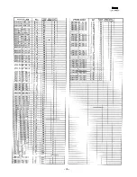
Страница 72: ...KNBZ68ggBHZz 1 36 AH c JKNBZ6g07BHzz 1 38 AK c J KNBZ6g08BHzz 1 38 AK c J KNBZ6gOgBHzz 1 38 AK c JK NBZ6g10BHzz 1 38 AL c JK NBZ6911BHzz 1 38 AK c JK NBZ6912BHZz 1 38 AK c JK NBZ6913BHzz 1 38 AK c JK NBZ6g14BHzz 1 38 AK c JK NBZ6g15BHzz 1 38 AK c JK NBZ6916f3Hzz 1 38 AK c JK NBZ6917BHzz l AK c JK NBZ6g18BHzz 1 38 AK c JK NBZ6glgBHzz 1 38 AK c JK NBZ6920BHzz 1 AK rKl c L 89 4 Ki UB6778Rczz I 3 11 L...

Страница 73: ...UIHH1 50J 8 16 I AA r VCCCTV1HH200J 9 2 A l l VCCSPU1HL470J 6 59 VCEAEU CW106M 8 17 VCEAGA1CW107M 6 45 VCEAGAI VCEAGA1CW477M 6 40 n VI VCEAGAIHW1 05M 6 45 AB cl VCEAGA1HW106M I 6 43 I AA c i VCEAGA1HW107M I 6 39 AA c VCEAGA1HW228M c 7C VCEAGA1 VCEAGA1HW476M i 57 VCEAGU1HW478M s 77 VCKYCYIHB102K 9 3 I wJ AD i i lQn 44 4 I A I I QCNCM7178BHew I II I MM I I I QCNCM7178BH3F 6 91 AL nP NPh 7370nunK i n...

Страница 74: ...g3J 9 20 AA c VRS Ts2AD432J 9 21 AA c VRS Ts2AD j63J 9 27 AA c VRS TS2AD622J 9 22 AA c VRS TS2AD623G 9 23 AB c VRS TS2AD821J 9 26 AA c 1 B l 6 37 AA B Y D 0c 8 22 AA B SDSCOO VSDSCOO Dzb VSUMX5 LAA I XBBSC30P06000 1 8 AA c f 2 8 AA c XBBSC30P20000 3 22 AA c XBPSD3nP06r 00 6 Q7 AA c PARTS CODE NO PRICE NEW PART RANK MARK RANK XBPSD3OP1OOOO 6 71 AA c XBPSD40P06KO0 4 44 AA c XBPSD40P06000 4 47 AA c X...

Страница 75: ...roduced stored in a retrieval system or transmitted in any form or by any means electronic mechanical photocopying recording or otherwise without prior written permission of the publisher SHARP CORPORATION Information SystemsGroup Quality Reliability Control Center Yamatokoriyama Nara 639 11 Japan 1995 NovemberPrinted in Japan ...

Отзывы: