CHAPTER 8. IPL (Initial Program Loading) FUNCTION
The application program of the ER-A220 is written on the CPU internal
FLASH ROM.
When servicing the unit, it is necessary to write the application pro-
gram on the CPU internal FLASH ROM.
When the CPU is changed :
The following CPUs delivered as service parts do not have the
application program written on them.
PARTS NAME
PARTS CODE
LOCATION No.
CPU
IC8
When the application program is changed, such as when the ver-
sion is updated.
Use the MASTER ROM (EP-ROM : 256 kbyte) to write the applica-
tion program.
PARTS NAME
PARTS CODE
LOCATION No.
MASTER ROM
Attach to the IC
socket of IC2.
IPL operating procedure
Power off the ECR.
Set the short pin : SP1 to the IPL mode on the main PWB
Install the MASTER ROM (EP-ROM) to the IC SOCKET : IC2 on
the main PWB
Power on the ECR.
Enter the Service rest.
(Turn the Mode switch from SRV’ to SRV position.)
When writing is finished, power off the ECR.
Return the short pin:SP1 to the Normal mode.
Remove the MASTER ROM (EP-ROM) from the IC socket:IC2.
Power on the ECR.
Master reset.
(While holding down PAPER FEED key, Mode switch turn to SRV’
position to SRV position. )
IC2:Install the MASTER ROM (EP-ROM)
SP1 : IPL mode
Normal
IPL
IPL mode
Service reset starts
The CPU operating clock is set.
(2 multiplies of the main clock
are selected)
Control moves to memory
expansion mode.
External bus software wait + 1
is set.
Master ROM data is confirmed.
If the external ROM data is
correct, writing starts.
When writing is finished, the
buzzer sounds (3 short beeps).
If the external ROM data is not
correct, the buzzer keeps
sounding (requesting resetting).
By setting SHORT PIN:SP1, the
CPU runs into the IPL mode.
IPL program is copied from
Master ROM to the CPU internal
RAM.
Control jumps to the copied
program on the CPU internal
RAM.
Содержание ER-A220
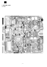
Страница 35: ...5 MAIN PWB LAYOUT 1 Side A ...
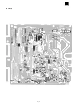
Страница 36: ... 2 Side B ...
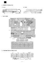
Страница 37: ...6 PRINTER I F PWB LAYOUT 1 Side A 2 Side B 7 KEY I F PWB 8 CUSTOMER DISPLAY PWB LAYOUT ...


