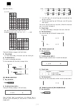
7. Operational method
1) To prepare an ECR to receive data from another ECR or the ER-
02FD, the memory size of the receiving unit must the same as or
greater than the sending unit.
2) Master reset the receiving ECR.
3) Connect loader cable between ECRs.
4) Set the receiving ECR ready to receive.
5) Start the sending ECR.
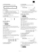
6) Transmission status.
Description of error status
1 : Application error (Command error)
2 : Application error (Parity error)
3 : Application error (Check sum error)
4 : Application error (Data size error)
5 : Hard ware error
6 : Power off error
7 : Time out error
8 : DSR off error(when data transmission starts)
11 : Application error (Transmit data size error)
12 : Application error (Block sequence error)
15 : Application error (different model error)
7) Service reset the receiving ECR.
8. Saving/Loading of data to/From the FD
unit Configuration
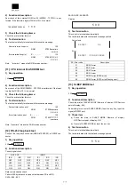
1) Turn off the power switch of the ER-02FD, and set the DIP
switches of the FD unit as follows:
ER-02FD (The ER-01FD functions of the ER-02FD are
used.)
2) Connect the cable.
Saving data
1) Turn on the power switch and insert a floppy disk which has been
formatted.
2) Start the SEND JOB on the ECR side as follows:
3) Data transmission is started and the green lamp on the ER-02FD
blinks.
Loading data
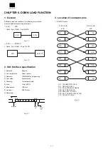
1) Turn on the power switch and insert the floppy disk which stores
the data.
2) Start the RECEIVE JOB on the ECR side as follows:
3) Press the SEND key on the FD unit.
4) Data transmission is started and the Green lamp on the ER-02FD
blinks.
5) Service reset the ECR.
96
X
#/TM/ST
TL/NS
98
X
#/TM/ST
TL/NS
OFF ON OFF OFF OFF ON
X
ON OFF OFF
OFF ON
DS-1
1
2
3
4
5
6
7
8
1
2
3
4
DS-2
Data rate
4
6
Rate [bps]
OFF
OFF
19200
Disk format
CCP/M: OFF
PC-DOS: ON
ON
OFF
9600
96
X
#/TM/ST
TL/NS
98
X
#/TM/ST
TL/NS
Содержание ER-A220
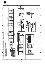
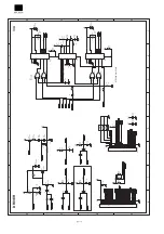
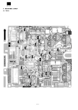
Страница 35: ...5 MAIN PWB LAYOUT 1 Side A ...
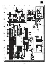
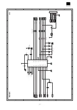
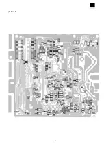
Страница 36: ... 2 Side B ...
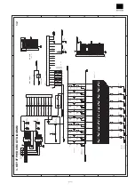
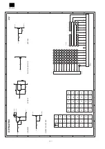
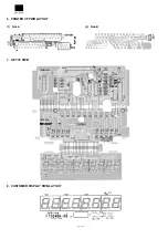
Страница 37: ...6 PRINTER I F PWB LAYOUT 1 Side A 2 Side B 7 KEY I F PWB 8 CUSTOMER DISPLAY PWB LAYOUT ...


