49
DV-L70S
DV-L70BL
DV-L70W
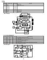
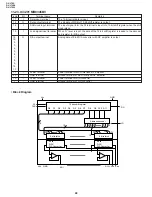
9-24. IC3202 BR93L46F
EEPROM
Terminal
Terminal name
In/Output
Function
2
VCC
–
Power
7
GND
–
All input/output reference voltage, 0V
3
CS
Input
Tip select input
4
CLK
Input
Sirial clock input
5
DIN
Input
Start bit, operation code, address and serial data input
6
OCNT
Output
Serial data output, READY/BUSY internal status indication output
• Block Diagram
C S
S K
D I
D O
Dummy bit
Instruction
register
Data
resistor
R/W
Amp.
Address
buffer
Address
Decoder
Instruction decode control
clock generation
Wave voltage
detection
Write
inhibition
High voltage
generation
bit
EEPROM
Aray
1,024
6bit
6bit
16bit
16bit
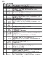
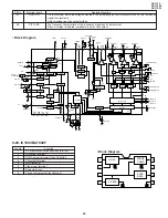
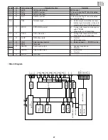
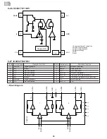
9-25. IC3205 S875045B
Voltage detection
circuit
Phase fault
protection circuit
Delay circuit
1
4
2
3
5
V
OUT
V
OR
V
IN
V
SS
C
D
Voltage
regulator
Pin No. Terminal name
Remarks
1
V
OUT
Output terminal of voltage regulator
2
Vss
GND terminal
3
C
D
External capacitor connection terminal for
delay of voltage detection circuit
V
PF
Power-off circuit input terminal
SENSE
Voltage monitor terminal of voltage detection
circuit
4
V
OR
Output terminal of voltage detection circuit,
Nch open drain
5
V
IN
Positive power input terminal
Содержание DV-L70BL
Страница 2: ...DV L70S DV L70BL DV L70W 2 1 IMPORTANT SAFEGUARDS AND PRECAUTIONS ...
Страница 6: ...DV L70S DV L70BL DV L70W 6 For details on the use of each control 4 PART NAMES ...
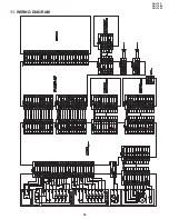
Страница 53: ...53 DV L70S DV L70BL DV L70W 11 WIRING DIAGRAM ...
Страница 80: ...Ref No Part No Description Code Ref No Part No Description Code 93 DV L70S DV L70BL DV L70W M E M O ...
Страница 81: ...Ref No Part No Description Code Ref No Part No Description Code 94 DV L70S DV L70BL DV L70W M E M O ...
Страница 82: ...Ref No Part No Description Code Ref No Part No Description Code 95 DV L70S DV L70BL DV L70W ...


