47
DV-L70S
DV-L70BL
DV-L70W
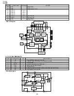
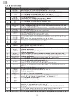
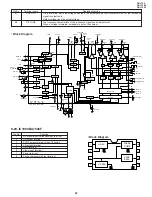
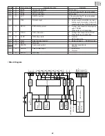
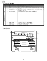
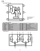
Pin No.
I/O
Terminal name
Operation function
Remarks
52
O
LED1
LED control (green)
LED control
53
O
AV S
DVD/TV control
“H” is output during TV tuner reception.
54
O
LED2
LED control (red)
LED control
55
O
AV P
DVD/TV control
“H” is output during TV tuner reception
and external input.
56
DEF
Defeat output
H ... External synchronization (normal)
L ... Internal synchronization (in the auto
preset mode/during OSC adjustment)
57
O
EPCS
EPROM chip select
H ... During data transmission/reception
with E
2
PROM
L ... When data is not transmitted.
58
O
DACS
DAC chip select
H ... During data transmission to DAC
L ... When data is not transmitted.
59
O
FLOF
DVD video mute
H ... Normal
L ... DVD video mute
60
O
IN H
External input control
H ... External input, L ... DVD/TV mode
61
I
PSW
Not used.
62
O
SMUTE
Audio mute output
L ... Speaker sound mute
63
H ... Normal
65
O
PMUTE
Video mute output
L ... Video mute
H ... Normal
79
O
FMCS
Not used.
Timer
RAM
(512byte)
ROM
(32Kbyte)
It is
interrupted.
CGRAM
ADDRESS BUS
DATA BUS
CGROM
OSD CONTROL
SIO
A/D
D/A(PWM)
PORT I/O
CLOCK
GENERATOR
SYSTEM
CONTROL
VDD
GND
CPU
(SM83 core)
33
32
66
ACL
T1
T2
CL1
CL0
P00
69
70
68
67
19
P07
12
P10
53
P17
60
P20
30
P27
20
P30
61
P32
65
P33
11
P37
7
P40
42
P47
52
P50
36
P54
40
P55
35
P56
34
P57
31
VSVNC
6
HSYNC
5
P64/BLK
2
P63/I
79
P60/R
78
P61/G
77
P62/B
76
OSC0
75
OSC1
74
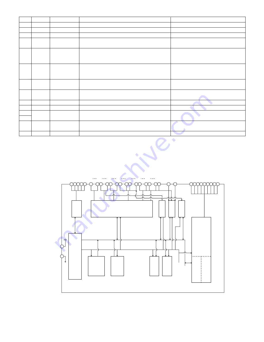
• Block Diagram
Содержание DV-L70BL
Страница 2: ...DV L70S DV L70BL DV L70W 2 1 IMPORTANT SAFEGUARDS AND PRECAUTIONS ...
Страница 6: ...DV L70S DV L70BL DV L70W 6 For details on the use of each control 4 PART NAMES ...
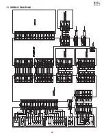
Страница 53: ...53 DV L70S DV L70BL DV L70W 11 WIRING DIAGRAM ...
Страница 80: ...Ref No Part No Description Code Ref No Part No Description Code 93 DV L70S DV L70BL DV L70W M E M O ...
Страница 81: ...Ref No Part No Description Code Ref No Part No Description Code 94 DV L70S DV L70BL DV L70W M E M O ...
Страница 82: ...Ref No Part No Description Code Ref No Part No Description Code 95 DV L70S DV L70BL DV L70W ...


