CVP09LX
2 – 3
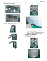
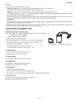
10.Remove the cabinet by lifting it up and pulling toward you as shown
in below figure.
11. Unscrew 4 screws holding the control box cover.
12.Remove the control box cover, as shown in below figure.
CAUTION: DISCHARGE THE FAN MOTOR CAPACITOR AND RUN-
NING CAPACITOR BEFORE TOUCHING THESE CAPAC-
ITORS OR OTHER COMPONENTS OR WIRING.
13.Unscrew 2 screws holding the float switch ass’y.
Then move the float switch a little from bulkhead L.
14.Unscrew 6 screws holding the bulkhead L.
Remove the wire from wire holder.(2 parts)
Then remove the bulkhead L by pulling it toward the arrow mark in
below figure and next lift it up toward you.
Содержание CV-P09LX
Страница 3: ...CVP09LX 1 2 3 WIRING DIAGRAM 4 EXTERNAL DIMENSION M M TH2 TH1 TH3 18 5 15 1 16 1 32 3 0 95 Max 59 ...
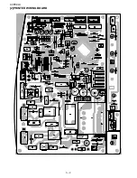
Страница 16: ...CVP09LX 3 2 2 PRINTED WIRING BOARD ...
Страница 51: ...MEMO ...


