CVP09LX
2 – 7
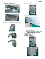
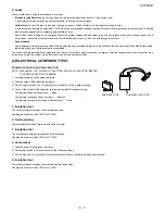
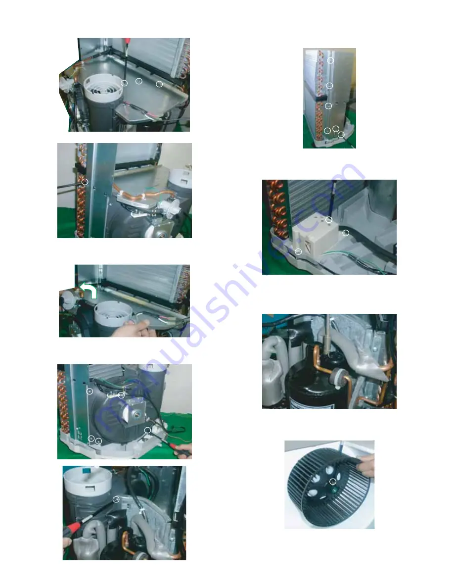
34.Unscrew 4 screws holding the half plate.
Then remove the half plate by lifting it up and pulling toward you as
shown in below figure.
35.Unscrew 6 screws holding the out casing.
Remove the out casing from the unit.
36.Unscrew 6 screws holding the stay angle R.
Remove the stay angle R from the unit.
37.Unscrew 3 screws holding the drain pump ass’y.
Remove the drain pump ass’y from the unit.
38.Unfasten and remove the nut holding the terminal cover at the top
of compressor.
Then remove the wiring connector of the compressor cord.
39.Unscrew the screw holding the centrifugal fan.
Remove the centrifugal fan.
Содержание CV-P09LX
Страница 3: ...CVP09LX 1 2 3 WIRING DIAGRAM 4 EXTERNAL DIMENSION M M TH2 TH1 TH3 18 5 15 1 16 1 32 3 0 95 Max 59 ...
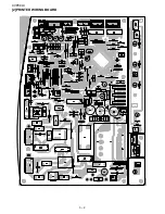
Страница 16: ...CVP09LX 3 2 2 PRINTED WIRING BOARD ...
Страница 51: ...MEMO ...


