background image

INSTALL WINDOW PANEL

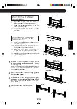
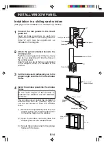
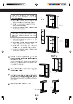
Installation in a sliding sash window

(See page 12 for installation in a double-hung window.)

Hole

Projection

Insect guard net

Rain guard

"A"

Window panel

Projection

"A"

Window
panel

E-14

Adjustment panel

Exhaust cover

Window 
panel

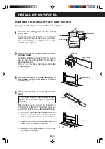
1

Connect the rain guards to the insect

guard net.

Insert all three projections on each rain

guard into the holes in the insect guard net.

Side “A” will now be uppermost, as

indicated in the diagram.

2

Attach the guard combined above to the

window panel.

Push the insect guard net firmly to ensure

that its four projections fit into the holes in
the window panel.

Side “A” will now be at the top, as indicated

in the diagram, when it is installed in the
window.

3

Cut the foam seal A (adhesive type) to the

proper length and attach it to the window
frame.

4

Install the window panel into the window

frame.

If the inner height of the window is
between 22" (559mm) and 24" (609mm)
inclusive.

The window panel cannot be installed in
windows less than 22" (559mm) high, as
you will be unable to shut the exhaust
cover.

(1) Remove the adjustment panel from the

window panel, and cut the window panel
to the same height as the window.

(2) Open the window sash and place the

window panel on the window frame.

(3) Secure the window panel to the window

frame with 2 screws.

Cut

22"~24"

Foam seal A
(adhesive type)

Содержание CV -P09FX

Страница 1: ...ER INSTALLATION AND OPERATION MANUAL CLIMATISEUR DE CHAMBRE DE TYPE PORTATIF MANUEL D INSTALLATION ET D UTILISATION Plasmacluster is a trademark of SHARP Corporation Plasmacluster est une marque de commerce de SHARP Corporation FRANÇAIS ENGLISH ...

Страница 2: ......

Страница 3: ...STALL WINDOW PANEL E 12 INSTALLATION AND REMOVAL OF EXHAUST HOSE E 16 PRE OPERATION CHECKS E 18 COOL MODE E 20 DEHUMIDIFICATION MODE E 21 FAN MODE E 22 VENTILATION MODE E 22 TO CHANGE AIR FLOW DIRECTION E 23 PLASMACLUSTER OPERATION E 24 MEGA COOL OPERATION E 25 ONE HOUR OFF TIMER E 25 TIMER OPERATION E 26 AUXILIARY MODE E 28 DRAINAGE E 29 MAINTENANCE E 30 BEFORE CALLING FOR SERVICE E 31 E 1 Declar...

Страница 4: ... Authorized Servicer PARTS for your Authorized Parts Distributor ACCESSORIES ADDITIONAL CUSTOMER INFORMATION TO WRITE For service problems warranty information missing items and other assistance Sharp Electronics Corporation Customer Assistance Center 1300 Naperville Drive Romeoville IL 60446 1091 TO ACCESS THE INTERNET www sharpusa com Please provide the following information when you write or ca...

Страница 5: ...escribed herein shall constitute complete fulfillment of all liabilities and responsibilities of Sharp to the purchaser with respect to the Product and shall constitute full satisfaction of all claims whether based on contract negligence strict liability or otherwise In no event shall Sharp be liable or in any way responsible for any damages or defects in the Product which were caused by repairs o...

Страница 6: ... Authorized Servicer PARTS for your Authorized Parts Distributor ACCESSORIES ADDITIONAL CUSTOMER INFORMATION TO WRITE For service problems warranty information missing items and other assistance Sharp Electronics of Canada Ltd Customer Care 335 Britannia Road East Mississauga Ontario L4Z 1W9 TO ACCESS THE INTERNET www sharp ca Please provide the following information when you write or call model n...

Страница 7: ...iod warranty service may be obtained upon delivery of the Sharp product together with proof of purchase and a copy of this LIMITED WARRANTY statement to an Authorized Sharp Service Centre or an Authorized Sharp Servicing Dealer In home warranty service may be provided at Sharp s discretion on any Sharp television with the screen size of 27 or larger and on any Sharp Over the Range Microwave Oven T...

Страница 8: ...duct a Power Plug Check See Page 18 before use to confirm the power plug functions normally This power plug must only be plugged into an appropriate wall socket Do not use in conjunction with any extension cords Push the power plug securely into the socket and make sure it is not loose Do not pull deform or modify the power supply cord or immerse it in water Pulling or misuse of the power supply c...

Страница 9: ...ng pin 3 Pin plug Grounded socket box 3 Pin socket USAGE CAUTIONS Ventilate the room periodically during use especially if using gas appliances Be sure to turn the unit off and disconnect the power supply cord before performing any maintenance or cleaning Do not splash or pour water directly onto the unit Water can cause electrical shock or equipment damage Drainage should be performed whenever mo...

Страница 10: ... dehumidification mode and the room temperature will rise Warm air will be blown out from the Exhaust air outlet but this is normal and does not indicate a problem with the unit This air conditioner blows the warm air generated by the unit outside the room via the exhaust hose while in cool mode Accordingly the same amount of air as that blown out will enter the room from outside through any openi...

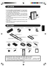
Страница 11: ...r outlet of the unit Allow at least 12 30cm of space from the wall for effi cient air conditioning MIN 12 30cm MIN 12 30cm INCLUDED SUGGESTED TOOLS FOR WINDOW PANEL INSTALLATION 1 Screwdriver medium size Phillips 2 Tape measure or ruler 3 Knife or scissors 4 Saw In the event that the window panel needs to be cut down in size because the window is too narrow for direct installation E 9 Bracket 1 Sc...

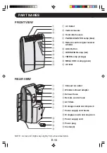
Страница 12: ... COOL Lamp green 0 Air inlet REAR VIEW NOTE Actual unit might vary slightly from above illustration FRONT VIEW q Exhaust air outlet w Window exhaust adapter e Exhaust hose r Remote control hook t Air filters y Drainage nozzle and stopcock u Power supply cord hooks i Drainpipe nozzle and stopcock o Power supply cord p Power plug a Casters 4 E 10 1 2 3 4 5 6 7 8 9 0 0 0 q w e r t y u i o p a ...

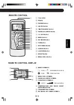
Страница 13: ...q OFF TIMER Button w CANCEL Button e LOUVERS Button r RESET Button t MEGA COOL Button E 11 y MODE SYMBOLS COOL DEHUMIDIFICATION FAN VENTILATION u MEGA COOL SYMBOL i PLASMACLUSTER SYMBOL o FAN SPEED SYMBOLS AUTO Manual setting p TEMPERATURE AND TIMER COUNT DOWN INDICATOR a TRANSMITTING SYMBOL s ON TIMER OFF TIMER SYMBOL REMOTE CONTROL DISPLAY 1 2 3 4 5 6 7 8 9 0 q w e r t y u i o p a s ...

Страница 14: ...uard net firmly to ensure that its four projections fit into the holes in the window panel Side A will now be at the top as indicated in the diagram 3 Cut the foam seal A adhesive type to the proper length and attach it to the window stool 4 Attach the window panel to the window stool If the inner width of the window is be tween 22 559mm and 24 609mm inclusive The window panel cannot be installed ...

Страница 15: ...ce the win dow panel on the window stool 3 Slide the adjustment and extension panels to fit the window frame width 4 Secure the window panel to the window stool with 4 screws 5 Cut the foam seals adhesive type A and B to the proper length and attach it to the window panel Attach foam seal A to the window panel and extension panel and attach foam seal B to the adjustment panel 6 Close the window sa...

Страница 16: ...ojections fit into the holes in the window panel Side A will now be at the top as indicated in the diagram when it is installed in the window 3 Cut the foam seal A adhesive type to the proper length and attach it to the window frame 4 Install the window panel into the window frame If the inner height of the window is between 22 559mm and 24 609mm inclusive The window panel cannot be installed in w...

Страница 17: ...ide the adjustment and extension panels to fit the window frame height 4 Secure the window panel to the window frame with 4 screws 5 Cut the foam seals adhesibe type A and B to the proper length and attach them to the window panel Attach foam seal A to the window panel and extension panel and attach foam seal B to the adjustment panel 6 Close the window sash securely against the Window panel 7 Cut...

Страница 18: ... are securely attached afterwards 2 Attach the exhaust hose adapter to the unit Insert the two projections on the exhaust hose adapter into the two holes on the unit and firmly attach them to each other 3 Slide and open the exhaust cover on the window panel and attach the win dow exhaust adapter Surface of window exhaust adapter marked TOP should be at the top when it is installed in a double hung...

Страница 19: ...haust adapter Pull out and remove the window exhaust adapter by pushing down two PUSH markings and slide and close the exhaust cover in the window panel 2 Remove the exhaust hose adapter from the unit Lift up and remove the exhaust hose adapter from the unit by pushing down on the two projections ...

Страница 20: ... button using a thin pointed implement If you will not be using the unit for a prolonged period remove the batteries from the remote control LOADING BATTERIES Use two AAA R03 batteries Battery cover PRE OPERATION CHECKS RESET POWER PLUG CHECK This air conditioner uses a fused power plug Always check the power plug before use 1 Press the RESET button 2 Insert the power plug into the wall socket 3 P...

Страница 21: ...sed to direct sunlight or near a heater Pro tect the remote control from moisture and shock which can discolor or damage it Point the remote control towards the units signal receiver window and press the desired button A beep will sound when the unit receives the signal Make sure nothing such as curtains blocks the signal receiver window The remote control operates up to 23 feet 7 meters away HOW ...

Страница 22: ...L mode COOL DEHUM FAN VENT 2 Press the POWER button to start op eration The red OPERATION lamp on the unit will light 3 Press the TEMPERATURE button to set the desired temperature The temperature can be set within the range of 64 F to 86 F 4 Press the FAN button to set the de sired fan speed AUTO QUIET LOW HIGH TO TURN OFF Press the POWER button again The red OPERATION lamp on the unit will turn o...

Страница 23: ...ion with no container E 21 2 1 In this mode the air conditioner dehumidifies the room CAUTION When operating dehumidification with container the unit generates heat during dehumidifica tion mode and the room temperature will rise Operate dehumidification with no container if you don t want the room temperature to rise This will help to slightly drop the room temperature but dehumidification perfor...

Страница 24: ...HUM FAN VENT 2 Press the POWER button to start operation The red OPERATION lamp on the unit will light The temperature cannot be set 3 Press the FAN button to set the desired fan speed QUIET LOW HIGH TO TURN OFF Press the POWER button again The red OPERATION lamp on the unit will turn off 1 Press the MODE button to select VENT mode COOL DEHUM FAN VENT 2 Press the POWER button to start operation Th...

Страница 25: ...ized and the same position will be set automatically when operated the next time LEFT RIGHT AIR FLOW DIRECTION CAUTION Never attempt to adjust the horizontal louvers manually Manual adjustment of the horizontal louvers can cause the unit to malfunction when the remote control is used for adjustment When the horizontal louvers are positioned at the lowest position in the COOL or DEHUMIDIFICA TION m...

Страница 26: ...function will be memo rized and it will be activated the next time you turn on the air conditioner To turn off the PLASMACLUSTER Lamp press the LIGHTS button PLASMACLUSTER operation cannot be set during VENTILATION mode PLASMACLUSTER OPERATION The Plasmacluster ion generator inside the air conditioner will release positive and negative Plasmacluster ions into the room Approximately the same number...

Страница 27: ...the unit will turn off Alernatively turn the unit off by pressing the POWER button The red OPERATION lamp and the orange TIMER lamp on the unit will turn off 1 When the ONE HOUR OFF TIMER is set the unit will automatically turn off after one hour ONE HOUR OFF TIMER NOTES The ONE HOUR OFF TIMER operation has priority over ON TIMER and OFF TIMER operations If the ONE HOUR OFF TIMER is set while the ...

Страница 28: ...e power is restored The unit will turn off automatically according to your setting Timer duration can be set from a minimum of half an hour 30 minutes to a maximum of 12 hours Up to 9 5 hours you can set in half hour 30 minutes increments and from 10 to 12 hours in 1 hour increments TIMER OPERATION OFF TIMER 1 Point the remote control at the signal receiver win dow on the unit 1 Press the OFF TIME...

Страница 29: ...ge as you press the button as follows Hold the button down to speed through the set tings The orange TIMER lamp on the unit will light The unit will emit a beep when it receives the signal The time setting will count down to show the re maining time TO CANCEL TIMER Press the CANCEL button The orange TIMER lamp on the unit will turn off Select the mode temperature fan speed setting and PLASMACLUSTE...

Страница 30: ...ode The fan speed is set to AUTO The temperature setting is automatically set according to the room temperature TO TURN OFF Press the AUX button again The red OPERATION lamp on the unit will turn off NOTES If the AUX button is pressed during normal operation the unit will turn off Upon starting AUXILIARY operation the drainage pump inside the unit runs for about a minute which may produce an audib...

Страница 31: ...ff by pressing AUX button This would take about one minute 8 Remove the hose from the drainage nozzle and replace the stopcock Keep the hose clamp and drain grommet in case of re used 9 Turn the drainage nozzle to the CLOSE position Whenever the unit is moved to provent water within the unit from spilling When the unit is not used for a long time 1 Carry out the above procedures from 1 to 5 2 Pres...

Страница 32: ... insect guard net becomes clogged with dust Periodically remove the window exhaust adapter from the window panel and clean the insect guard net with a vacuum cleaner or suchlike Filters E 30 Be sure to disconnect the power from the wall socket before performing any mainte nance CLEANING THE FILTERS If the filter is clogged with dust the airflow will be reduced resulting in poor cooling perform anc...

Страница 33: ...The unit may seem rather loud for the first 2 to 3 minutes when the unit is turned on This is the sound of the compressor starting up and is perfectly normal A soft swishing noise can be heard immediately after the unit is turned on or off and also during operation This is the sound of the refrigerant flowing inside the unit A low buzzing noise is emitted when the unit is generating Plasmacluster ...

Отзывы: