CD-C471
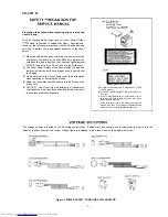
Precaution to be taken when replacing and servicing the
Laser Pickup.
The AEL (Accessible Emission Level) of Laser Power Output
model is specified to belowerthan Class Requirements.
However, the following precautions must be observed during
servicing to protect your eyes against exposure to the Laser
beam
(1) When the cabinet has been removed, the power is turned
on without a compact disc, and the Pickup is on a position
outerthan the lead-in position, the
Iightforseveral
to detect a disc, Do not look into the Pickup Lens.
(2) The Laser Power Output of the Pickup inside the unit and
replacement service parts have already been adjusted prior
to shipping.
(3) No adjustment to the Laser Power should be attempted
when replacing or servicing the Pickup.
(4) Under no circumstances look directly into the Pickup Lens
at any time.
(5) CAUTION Use of controls or adjustments, or performance
of procedures other than those specified herein may result
in hazardous radiation exposure.
Laser
Properties
Material:
Wavelength. 780
Emission
continuous
Laser Output: max. 0.6
This Mini Component System is classified as a CLASS
LASER product.
The CLASS LASER PRODUCT label is located on the
rear cover.
l
Use of controls, adjustments or performance of proce-
dures other than those specified herein may result in haz-
ardous radiation exposure.
As the laser beam used in this compact disc player is
harmful to the eyes, do not attempt to disassemble the
cabinet. Refer servicing to qualified personnel only.
The voltage selector is located on the AC voltage selector box. If adjustment is necessary, use a screwdriver in order to turn the
selector in either direction the correct voltage figure is displayed in the window next to the adjustment screw.
Figure 2 POWER SUPPLY CORD AND PLUG ADAPTOR
Содержание CD-C471 W
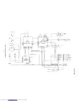
Страница 16: ... I I Ill I i c r __ __ I Figure 16 BLOCK DIAGRAM 2 3 16 ...
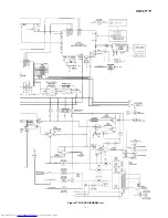
Страница 17: ...CD C471 W w UTER lC56115621563 N5M4558L lC562 1 2 Figure 17 BLOCK DIAGRAM 3 3 17 ...
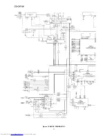
Страница 20: ...CD C471 W l NOTES ON SCHEMATIC DIAGRAM can be found on page 14 1 2 3 4 5 6 Figure 20 SCHEMATIC DIAGRAM 3 13 20 ...
Страница 30: ...CD C471 W CD NORMAL REC OTHERCD NORMAL PLAY I 2 I 3 I 4 5 6 Figure 30 SCHEMATIC DIAGRAM 13 l 3 30 ...
Страница 31: ...CD C471 W 1 SWICH PWB A3 1 DISPLAY PWB A2 1 7 8 9 10 11 12 I Figure 31 WIRING SIDE OF P W BOARD l E 3 1 ...
Страница 36: ... POWER PWB B 1 MAII IUPWB P33 7 A 1 2 3 4 5 6 Figure 36 WIRING SIDE OF P W BOARD 6 8 36 ...
Страница 54: ...CD C471 W MEMO 54 ...
Страница 66: ...CD C471 W 620 12 614x2 hy2 x b16 226 L 235 234 609x2 611 236 SOLM2 1 2 3 4 5 6 CABINET EXPLODED VIEW 2 2 ll ...
Страница 69: ...CD C471 W WOOFER SPI L CH SP2 R CH SPI 2 904 1 I 2 I 3 I 4 I 5 I 6 SPEAKER EXPLODED VIEW 2 2 14 ...
Страница 70: ......
Страница 71: ...CD C471 W MEMO ...


