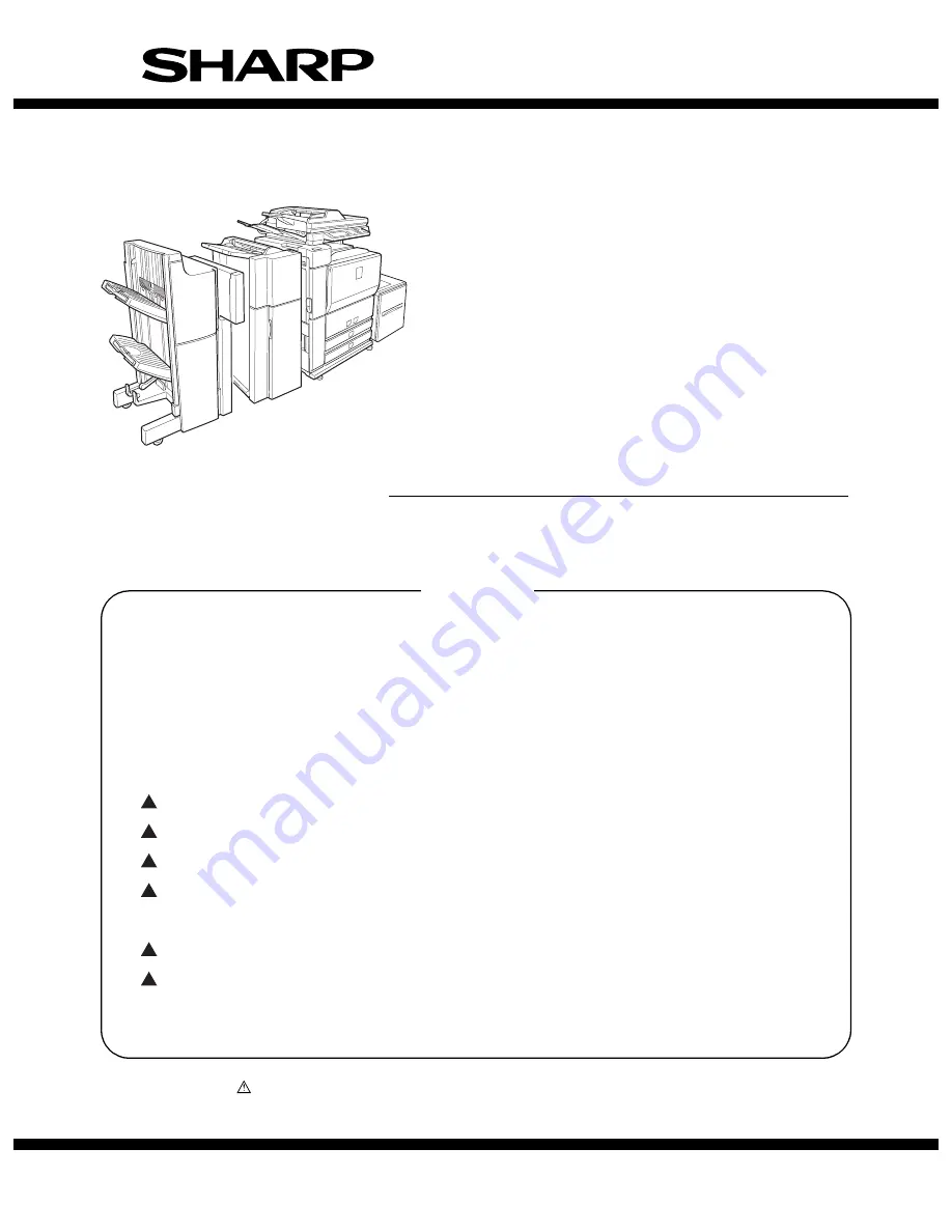
background image

CONTENTS

Parts marked with “

” are important for maintaining the safety of the machine. Be sure to replace these parts

with the replacement parts specified to maintain the safety and performance of the machine.

SHARP CORPORATION

This document has been published to be used
for after sales service only.
The contents are subject to change without notice.

INSTALLATION MANUAL

CODE : 00ZAR700//I1E

DIGITAL LASER COPIER/PRINTER
DIGITAL MULTIFUNCTIONAL SYSTEM

AR-M550N/M550U
AR-M620N/M620U

MODEL

AR-M700N/M700U

[ 1 ]  AR-M550/M620 UNPACKING AND INSTALLATION  . . . . . . . . . . 1 - 1

[ 2 ]  AR-LC6 UNPACKING AND INSTALLATION  . . . . . . . . . . . . . . . . 2 - 1

[ 3 ]  AR-CF2 UNPACKING AND INSTALLATION  . . . . . . . . . . . . . . . . 3 - 1

[ 4 ]  AR-F15/F16 UNPACKING AND INSTALLATION . . . . . . . . . . . . . 4 - 1

[ 5 ]  AR-PN4 UNPACKING AND INSTALLATION  . . . . . . . . . . . . . . . . 5 - 1

[ 6 ] AR-P19 INSTALLATION . . . . . . . . . . . . . . . . . . . . . . . . . . . . . . . . 6 - 1

[ 7 ] AR-FR11 INSTALLATION . . . . . . . . . . . . . . . . . . . . . . . . . . . . . . . 7 - 1

[ 8 ] AR-PK5 INSTALLATION . . . . . . . . . . . . . . . . . . . . . . . . . . . . . . . . 8 - 1

[ 9 ] AR-NS3 INSTALLATION . . . . . . . . . . . . . . . . . . . . . . . . . . . . . . . . 9 - 1

[10]  AR-FX8/AR-MM9 INSTALLATION  . . . . . . . . . . . . . . . . . . . . . . . 10 - 1

[11] MECHANICAL COUNTER INSTALLATION . . . . . . . . . . . . . . . . . 11-1

[12] DRY HEATER INSTALLATION . . . . . . . . . . . . . . . . . . . . . . . . . . . 12-1

1

1

1

1

2

2

Содержание AR M550N - B/W Laser - Copier

Страница 1: ...AL CODE 00ZAR700 I1E DIGITAL LASER COPIER PRINTER DIGITAL MULTIFUNCTIONAL SYSTEM AR M550N M550U AR M620N M620U MODEL AR M700N M700U 1 AR M550 M620 UNPACKING AND INSTALLATION 1 1 2 AR LC6 UNPACKING AND INSTALLATION 2 1 3 AR CF2 UNPACKING AND INSTALLATION 3 1 4 AR F15 F16 UNPACKING AND INSTALLATION 4 1 5 AR PN4 UNPACKING AND INSTALLATION 5 1 6 AR P19 INSTALLATION 6 1 7 AR FR11 INSTALLATION 7 1 8 AR ...

Страница 2: ...ed range use thicker lead wires to reduce impedance An electrical work is required Use of a step up transformer is also available In this case the capac ity must be great enough for the max power consumption of the machine 3 Power frequency waveform The frequency must be within the range of the specified frequency 2 If power waveform is deformed a trouble may occur 4 Safety Be sure to properly gro...

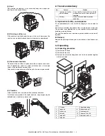
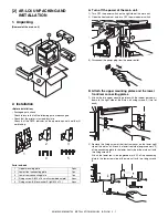
Страница 3: ...and delivery A Implements facility and manpower It is recommendable to use a forklift for bringing in the machine for safety If no forklift is available manpower of four or more persons is required The machine is considerably heavy and requires safety precautions for delivery and installation Transit of the machine must be made in packed condition to the install ing place B Delivery Remove the pac...

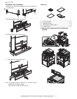
Страница 4: ...ers of the bottom case 6 Lift the machine slightly and remove the bottom pad L 7 Lift the machine slightly and remove the bottom pad R 8 Remove the slope Slope Parts 9 Attach the slope to the concave section of the skid 10 Hold the machine grips and push them down in the arrow direc tion Part name Part code Skid slope DKiT 0367FCZZ ...

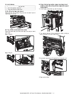
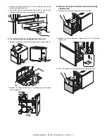
Страница 5: ... the main unit 3 Install the adjuster cover to the main unit 4 Insert the bottom tray into the main unit Note This machine includes a hard disk drive which must be pro tected against vibrations and shocks Never move the machine with the power ON Packed items C Remove the fixing tape and the reinforcing material 2 1 Driver CD ROM x 1 2 Operation manual x 1 3 Delivery and installation report x 1 4 P...

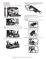
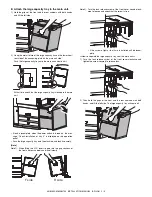
Страница 6: ...e label of note for tray Tray 1 Tray 2 Tray 3 Tray 4 E Press the fusing section upper and lower heat rollers and remove the process separation pawl fixing block 1 Pull the knob on the left door to pull out the left door 2 Turn the pressing screw in the fusing section as shown in the figure below fully loosen it to press the heat roller 3 Remove the separation pawl fixing block from the process uni...

Страница 7: ...loper from the developer supply port of the developing unit turn the MG gear clockwise with a plus screwdriver to supply all developer to the developing unit 7 Install the toner hopper to the developing unit 8 Insert the developing unit to the main unit and fix it with the blue screw 9 Close the process cover and fix it with the blue screw 2 Toner set 1 Remove the toner cartridge from the box and ...

Страница 8: ... paper so that the specified line is not exceeded 3 Slowly insert the tray 3 or the tray 4 3 Supply paper to the manual paper feed tray The manual paper feed tray is for 11 x 17 to 8 1 2 x 11 R size A3 size to A5R and special paper For the kinds of paper and special paper refer to the specifications of this manual 1 Open the manual paper feed tray Note When setting 11 x 17 8 1 2 x 14 8 1 2 x 13 or...

Страница 9: ...e with the A4 exclusive regulation plate 1 Remove the A4 exclusive regulation plate from the storage position left inside of the machine It is fixed with a fixing screw under the tab paper guide 2 Pull out the tray 1 and the tray 2 3 Remove the B5 size regulation plate and the rear edge regulation plates F and R from the tray 2 When removing the B5 size regulation plate slightly press the paper fe...

Страница 10: ...y 3 5 Push the tray 3 7 Setting the paper type and paper size Follow these steps to change the paper type setting when the paper type has been changed in a paper tray For the paper types that can be used in each tray 1 Press the CUSTOM SETTINGS key The custom setting menu screen will appear 2 Touch the TRAY SETTINGS key The paper tray selection screen will appear 3 Display the setting screen of th...

Страница 11: ...ed Note Special sizes of paper cannot be loaded in trays 1 2 4 and 5 Trays 3 and the bypass tray 1 Perform steps 1 through 5 of Setting the paper type and paper size 2 Touch the SIZE INPUT key and then touch the INCH tab The size entry palette appears 3 Touch the key or the key to enter the X width and Y length dimensions of the paper X width is initially selected To enter Y length touch the Y key...

Страница 12: ... size setting screen of step 2 5 Perform steps 7 through 10 of Setting the paper type and paper size H The other parts setting 1 Document exit tray installation Install the document exit tray to the scanner unit as shown in the figure below 2 Other notes Check to insure that the cable connected to the service terminal A in the figure below is 3m or less X AB Y 11 17 Y X INCH OK 5 1 2 17 inch 5 1 2...

Страница 13: ...oving the copier turn off the power and perform the following works 1 Remove the paper from the paper tray 2 Remove the developing unit from the main unit 3 Lock the position which was released at installation see the page 1 5 4 Remove the adjuster cover and raise the adjuster see the page 1 5 Note Since the main unit includes the hard disk drive be careful not to apply vibrations and shocks durin...

Страница 14: ...outlet B Attach the upper mounting plates and the lower front rear connecting plates 1 Attach the two upper mounting plates with the rubber portion down to the right side of the main unit using screws A two for each 2 Remove the fixing screw of the front rear cover on the lower right side of the main unit Attach the lower front side engraved mark F of the connecting plate to the lower front side o...

Страница 15: ...edure 3 C Fixing material and packaged part removal 1 Remove the fixing material from the large capacity paper feed tray 2 Remove the fixing material from the packaged part and remove the packaged part D Remove the paper feed base screw of the large capacity tray 1 Slowly pull out the paper feed base tray until it stops 2 Remove the paper feed base fixing screw 1 pc of the large capacity tray 3 Pu...

Страница 16: ...llation of tray 5 is displayed on the operation panel Push the large capacity tray onto the machine and lock it securely Note Note 1 When lifting the LCC insert fingers into the grip sections of the front and rear cabinets and install slowly Note 2 Turn the lock release screw of the front cover counterclock wise to loosen and check that the screw is free If the screw is tight at that time installa...

Страница 17: ...arge capacity tray 1 Remove the screw one for each from the connector cover on the main unit and then remove the two connector covers 2 Connect the large capacity tray interface harness connector and the heating heater interface harness connector to the main unit connector and tighten the connector screw to fix the connector H Select the paper size 1 Change A4 size to LT size The factory setting o...

Страница 18: ...Flat screw 1pc 3 Change the mark position of the auxiliary guide and the cas sette R from A4 to LT and fix them with the fixing screw flat screw 1pc At that time adjust so that the mark positions on the auxiliary guide and the cassette R are at the same positions of the mark positions of the side plate R and the size guide adjustment plate checked in the procedure 1 If the scale of the size guide ...

Страница 19: ...on I Turn the main power switch on the main unit to the ON position 1 Insert the power plug of the main unit to the outlet 2 Turn the main power switch to the ON position Then close the front cabinet cover 3 Turn ON the power switch on the right side of the main unit J Set the size Execute SIM 26 2 Size setting by the key operations of the main unit 1 The size selection menu of the large capacity ...

Страница 20: ...at shipping there is normally no need to adjust If the center is shifted however adjust with the simulation If the shift is not recovered perform the following steps to adjust 1 Pull out the large capacity tray until it stops 2 Loosen the stopper fixing screw 1 pc on the lower right side of the paper feed tray to disable the stopper function Adjustment position Set value Display item Item descript...

Страница 21: ...acity tray to the original position slowly Then make a copy again to check that the center is not shifted Repeat this procedure as required When shifted to the rear side When shifting the print line from the paper center in the arrow direction as shown below 4 Loosen the red fixing screws 2 pcs for each of the front back size guide adjustment plate and slide the side guide adjustment plate in the ...

Страница 22: ...ion after checking that the DATA indicator on the opera tion panel is neither lit nor blinking 1 Unpacking Removal of the main unit Removal of the parts included Removal of the fixing member 1 Remove the tape and open the upper door 2 Remove the tape and remove the miramatte 3 Remove the tape and remove the fixing member ...

Страница 23: ... power plug from the power outlet When the finisher F15 or the saddle finisher F16 is installed 2 Removal of the connector between the main unit and the finisher 1 Remove the screw from the finisher connector connected to the left side of the main unit 2 Disconnect the finisher connector Parts name Quantity 1 Positioning plate 1 pc 2 Upper limit regulation wire 1 pc 3 Button cover 1 pc 4 Screw C M...

Страница 24: ...screw for connection of the fin isher joint harness connector and remove the connector cover Only when the finisher and the inserter are installed together per form this procedure Note For fixing screws H and I use the packaged parts of the AR F15 F16 3 Attach the earth plate with the fixing screws H 2 pcs to the left lower section of the main unit In this case attach so that the R mark on the ear...

Страница 25: ...screw holes of the positioning plate and fix it with the three fixing screws C 6 Install the upper limit regulation wire to the inserter 7 Install the inserter to the finisher 1 Open the front door of the inserter and loosen the lock fixing screw until the screw is released 2 Stand the tray 3 Install the button cover with the lock button fixing screws D 2 pcs to hide the lock button on the top of ...

Страница 26: ...of the inserter lock to fix the inserter and the finisher 5 Check that the finisher lock lever is engaged on the inserter groove securely When the inserter cannot be installed to the finisher When the finisher and the inserter differ in the height perform the fol lowing height adjustment and insert the inserter 1 Set all the finisher height adjustment screws 4 positions to the center positions 2 I...

Страница 27: ...con nector and tighten the connector screw to fix it 2 Fix the finisher relay harness to the rear side of the inserter with two clamps 3 Connect the inserter relay harness connector to the main unit con nector and tighten the connector screw to fix the connector 11 Install the inserter to the main unit 1 Bring the inserter closer to the main unit 2 Check that the main unit positioning pin enters s...

Страница 28: ...stment bolt so that it is at the same position with the rear side adjustment section fixing screw 6 Tighten two fixing screws of the front side adjustment section 12 Finisher and inserter height adjustment 1 Check the height of the inserter front cabinet and the finisher front cabinet 2 Check the height of the inserter rear cabinet and the finisher rear cabinet When the height is proper Go to proc...

Страница 29: ...e height 1 Remove two screws which are fixing the base cover attached to the finisher rear side base section and remove the base cover 2 Loosen the adjustment section fixing screws 2 pcs 3 Use the spanner and adjust the height adjustment bolt so that the height of the rear side cabinet top surface is of the same height 4 Tighten the adjustment section fixing screws 2 pcs 5 Install the base cover 1...

Страница 30: ...h the spanner removed in step 1 so that the upper and the lower clearances are the same 5 Check that the upper and the lower clearances are even when viewed from the front and the back 6 Tighten the front and the rear side adjustment section fixing screws 2 pcs for each side 7 Install the base cover front and rear 8 Return the spanner to the original position 14 Install the plate At that time chec...

Страница 31: ...main power switch 1 Insert the power plug of the main unit to the outlet 2 Open the front cabinet and open the power cover 3 Turn ON the main power switch close the power cover and close the front cabinet 4 Turn ON the power switch on the right side of the main unit ...

Страница 32: ...p case 2 Remove the packaged parts from the add 3 Check the packaged parts Packaged parts 4 Hold the upper section of the machine with two persons and pull it up and stand it straight The machine is very heavy Be careful 5 Remove the tape and the skid 6 Remove the upper add 1 Positioning pin 1 pc 5 Staple label 2 pcs 2 Earth plate 1 pc 6 Screw G M4 x 6 3 pcs 3 Earth mounting plate 1 pc 7 Screw H M...

Страница 33: ...ittle and remove packing material on the opposite side 10 Slowly bring the base section of the machine on the opposite side to contact with the floor 11 Remove the vinyl cover 2 Fixing member removal Remove the taping from the finisher Remove the shipment locking material with red sticky note 1 Remove the tape 2 Remove the tape and remove the protection board and the sheet 3 Remove the tape and op...

Страница 34: ...the power cable fixing tape 10 Open the upper front door and remove the staple transit fixing member 11 Open the lower door and remove the each tape 12 Pull out the stitcher remove the screw and remove the stitcher transmit fixing member 13 Remove the screw and remove the lower cover 14 Remove the screw and remove the transit fixing members F and R 15 Remove the screw and remove lift tray rail sec...

Страница 35: ... the original state 7 Install the cabinet 8 Install the lift tray rail section fixing members 4 positions with four screws 2 Installation A Installation procedure 1 Turn off the power of the main unit 1 Turn OFF the power switch on the right side of the main unit 2 Open the front cabinet and turn OFF the main power switch 3 Disconnect the power plug from the power outlet 2 Attach the positioning p...

Страница 36: ...I 2 pcs 3 Plate and connection plate installation 1 Install the plate to the finisher as shown in the figure and fix it with the fixing screw G 1 pc 2 Install the rail and the finisher with two screws G M4 x 6 4 Caster adjustment A Bring the finisher closer to the main unit and check that the guide pin of the main unit enters into the connection hole in the finisher smoothly B At that time check t...

Страница 37: ...ters 5 Remove the spanner stored inside of the front cabinet upper and close the front cabinet upper 6 Turn the bolt with the removed spanner so that the guide pin is in the specified range of the scale At that time lift the finisher a little and the bolt can be turned man ually 7 After completion of the adjustment tighten the caster fixing screws 8 pcs and close the front cabinet lower 8 Check to...

Страница 38: ...nnection of the fin isher joint harness connector and remove the connector cover B Connect the finisher relay harness connector to the main unit con nector and tighten the screw on the connector to fix 7 Turn ON the main power switch 1 Insert the power plug of the main unit to the outlet 2 Open the front cabinet and open the power cover 3 Turn ON the main power switch close the power cover and clo...

Страница 39: ...in unit 2 Removal of the fixing member Packaged parts accessories 2 Installation 1 Turn off the power of the main unit 1 Turn OFF the power switch on the right side of the main unit 2 Open the front cabinet and turn OFF the main power switch 3 Disconnect the power plug from the power outlet Punch position label 2 pcs ...

Страница 40: ... 2 pcs on the rear side of the finisher and remove the rear cabinet B 3 Paper guide disassembly 1 Remove the paper guide fixing screw 1 pc and remove the paper guide from the finisher 4 Punch unit assembly 1 Hang the punch unit on the step screws 2 pcs of the finisher and assemble it 2 Fix the punch unit with the paper guide fixing screw 1 pc which was removed in step 3 5 Connector connection 1 Co...

Страница 41: ...fore hand This makes assembly eas ier 7 Position label attachment 1 Attach the punch position label as shown in the figure The label attachment position shown above is based on the corner of the cabinet 8 Finisher connector connection 1 Remove the connector cover fixing screw for connection of the fin isher joint harness connector and remove the connector cover 2 Connect the finisher joint harness...

Страница 42: ...STALLATION MANUAL AR PN4 5 4 2 Open the front cabinet and open the power cover 3 Turn ON the main power switch close the power cover and close the front cabinet 4 Turn ON the power switch on the right side of the main unit ...

Страница 43: ...inger to release the stopper pull the control PWB unit out of the main unit 3 Mount the printer expansion ROMs and a print server card to the control PWB 1 Remove the ROMs MAIN and BOOT ROMs from the control PWB and replace them with the two ROMs MAIN and BOOT ROMs of the printer expansion kit The MAIN and BOOT ROMs are indicated with MAIN and BOOT on the labels on the ROMs respectively When mount...

Страница 44: ... on the oper ation panel to enter the product key For entry of the product key see the section of key operator pro grams of the operation manual for the main unit After completing product key entry turn off the power switch and the main power switch of the main unit and then turn on the power switch and the main power switch of the main unit again 2 Carry out the network setting for the print serv...

Страница 45: ...f cables are connected to the control PWB remove all cables 2 Remove the four screws that secure the control PWB unit 3 Raise the two grips and hold them to pull out the control PWB unit until the stopper is engaged 4 Remove the two flat cable connectors 5 While using your finger to release the stopper pull the control PWB unit out of the main unit 3 Mount the data security kit ROMs to the control...

Страница 46: ...of the main unit to the outlet 2 Turn on the main power switch and then close the front cabinet 3 Turn the main switch located on the right side of the main unit to the ON position 6 Make preparations for enabling the data security function To enable the data security function use the keys on the operation panel to enter the product key For entry of the product key see the section of key operator ...

Страница 47: ... the sup plied CD ROM or the section of key operator programs of the operation manual for the main unit After completing product key entry turn off the power switch and the main power switch of the main unit and then turn on the power switch and the main power switch of the main unit again 2 Check the operation of the PS expansion function 1 Use the keys on the operation panel to execute test page...

Страница 48: ...e operation panel to enter the product key For entry of the product key see the section of key operator programs of the operation manual for the main unit After completing product key entry turn off the power switch and the main power switch of the main unit and then turn on the power switch and the main power switch of the main unit again 2 Check the operation of the scanner function 1 Installati...

Страница 49: ...to pull out the MFP control PWB unit until the stopper is engaged 4 Remove the two flat cable connectors 5 While using your finger to release the stopper pull the MFP control PWB unit out of the main unit Step for mounting extended memory AR MM9 If you need not mount an extended memory proceed to step 4 3 Mount an extended memory Mount an extended memory to the socket located on the back of the FA...

Страница 50: ... secure it with the two screws 8 Attach the FAX box unit Among the four screws shown in the illustration that secure the rear cabinet remove the lower two screws and loosen the upper two screws Then hang the FAX box unit on the two loosened screws and secure it with the two removed screws Finally tighten the two loosened upper screws to secure the FAX box unit 9 Connect the FAX power connector Rem...

Страница 51: ... the machine will be automatically rebooted and will start with the setting of the selected destination 13 Set the destination of the FAX 1 Switch the operation panel to the copy mode and use the key operation P C and to enter the simulation mode 2 Use the 10 key pad to enter 66 in the main code entry screen shown below and press the START key 3 Use the 10 key pad to enter 2 in the sub code entry ...

Страница 52: ... pad to enter 66 in the main code entry screen shown below and press the START key 3 Use the 10 key pad to enter 10 in the sub code entry screen shown below and press the START key 4 Use the 10 key pad to enter 1 in the submenu screen shown below and press the START key 5 The screen shown below is displayed and memory clear operation is executed 6 After several minutes memory clear operation is co...

Страница 53: ...0027FCZZ is treated as a service part When ordering order as a service part 1 Open the front cabinet of the main unit and cur off the counter cover with a cutter and pliers 2 Connect the connector on the mechanical counter side with the connector on the main unit side 3 Insert the mechanical counter into the main unit and fit it securely ...

Страница 54: ...ion 1 Loosen the screw and push down the metal fixture 2 Open the SPF and slide the SPF drop prevention stopper pin of the hinge L to the drop prevention position No Part name Part code Q ty 1 Dehumidifying heater switch QSW C1030QCZZ 1 2 Supporter LSUPP0118FCZZ 4 3 Dehumidifying heater relay PWB CPWBF1569FCE1 1 4 ACWH harness DHAI 3525FCZZ 1 1 2 2 2 3 No Part name Part code Q ty 1 Scanner dry hea...

Страница 55: ...ter 7 Install the clamp connect the SCN WH harness and pass it through the clamp and fix with the snap band 8 Install the clamp and install the dark box to the scanner base plate NOTE When installing the dark box check to insure that the blade spring is in the original position 9 Pass the SCN WH harness through the clamp and fix it with the snap band Connect the connector 2 4 3 4 2 1 3 5 5 6 5 5 5...

Страница 56: ...art name Part code Q ty 1 Heater mounting plate LPLTM6089FCZZ 1 2 Heater harness sheet PSHEZ5135FCZZ 1 3 Dry heater 120V Paper feed trays 1 2 RHETP0118FCZZ 1 Dry heater 230V Paper feed trays 1 2 RHETP0123FCZZ 4 Screw M3 x 8 XHBSD30P08000 3 5 Heater cover PCOVP1654FCZ1 1 6 Heater cover sheet PSHEZ5012FCZZ 1 7 Heat resistant clamp LHLDW0433FCZZ 1 8 Screw M4 x 8 XHBSE40P08000 1 8 1 6 5 3 4 4 2 7 No P...

Страница 57: ...nnector 4 Remove the lower stage of the paper trays 3 4 paper feed unit 5 Remove the paper feed lower cover 6 Install the dry heater paper feed trays 3 4 unit 7 Fix the harness with the snap band and pass it through the edge saddle 8 Connect the connector to the dehumidifying heater relay PWB 6 6 1 2 3 4 5 5 5 ...

Страница 58: ...tional one it is apt to keep the soldering iron in contact with the PWB for longer time This may cause land separation or may exceed the heat resistive temperature of components Use enough care to separate the soldering iron from the PWB when completion of soldering is confirmed Since lead free solder includes a greater quantity of tin the iron tip may corrode easily Turn ON OFF the soldering iron...

Страница 59: ...icant Swedish VARNING Explosionsfara vid felaktigt batteribyte Använd samma batterityp eller en ekvivalent typ som rekommenderas av apparattillverkaren Kassera använt batteri enligt fabrikantens instruktion German Achtung Explosionsgefahr bei Verwendung inkorrekter Batterien Als Ersatzbatterien dürfen nur Batterien vom gleichen Typ oder vom Hersteller empfohlene Batterien verwendet werden Entsorgu...

Страница 60: ...s Windows 95 Windows 98 Windows Me Windows NT 4 0 Windows 2000 and Windows XP are trademarks or copyrights of Microsoft Corporation in the U S A and other countries IBM and PC AT are trademarks of International Business Machines Corporation Acrobat Reader Copyright 1987 2002 Adobe Systems Incorporated All rights reserved Adobe the Adobe logo Acrobat and the Acrobat logo are trademarks of Adobe Sys...

Отзывы: