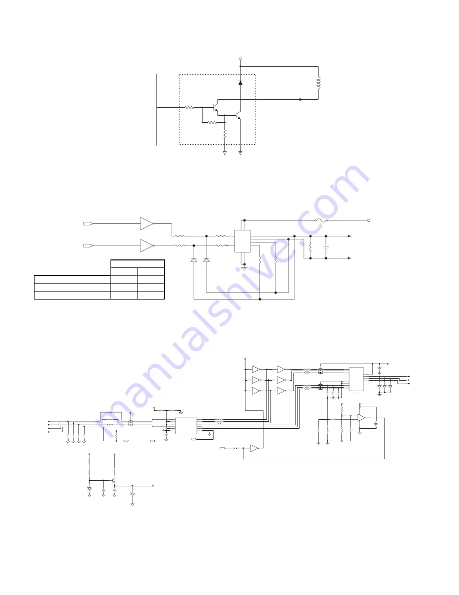
(4) Solenoid and clutch drive circuit
The solenoids and clutches are driven by a Darlington transistor array TD62004AP with 7-circuit clamp diode. LPFS is turned on when the CPU’s
port output is at H. LPFC has the same circuit.
(5) Lift motor drive circuit
The tray height is adjusted according to the size of the paper mounted on the paper feed tray. The lift motor controls the rotational direction
(CW/CCW) with the control signals (LLMU, LLMD) from the CPU. The circuit forms a bridge circuit with STA457C to allow the CW/CCW control.
A fuse (F01) is provided to protect the motor against shorting or overload.
Suppose that both LLMD and LLMU become H level at the above circuit. If LLMU becomes H first, the STA457C pin 3 become H, IC04 pin 13
through IC07 pin 6 become H due to diode D20. Even if LLMU is at H and LLMD at H on the port, STA457C pin 1 is at L and pin 6 at H, thus no
conduction of STA457C is achieved.
(6) Transport motor drive circuit
The motor drive circuit is composed of IC05 motor ICs (IC12, IC04 and IC06). When the PWM signal output from the CPU made at H level, the
transistor inside the IC06 turns on to supply current to the motor to start the motor. As the motor is started, hole signals (Hu, Hv, Hw) inside the
motor switch the input of IC05, while the output switches the transistor inside IC06. The motor thus starts rotating under non-control state.
When the motor rotates, the speed signal (RE) is output from the motor. The signal is taken into the CPU. If the motor speed is slow, the RWM
signal On duty is increased to increase the speed; if the motor speed is high, the PWM signal On duty is decreased to maintain the required speed.
As the current flowing to the motor becomes large, the input voltage at the minus side of the IC09 rises. If the voltage exceeds the plus-side input
voltage, output voltage at IC09 becomes at L level, leading in the PWM signal to turn off the transistor of IC07 so that the current to the motor is cut
off. (setting: 3A).
+24V
CPU(IC01)
P10/A0
SOL
LPFS/
CN-A-8
10.5K
7.2K
3K
48 LPFS
9A12004B
D21
1SS133x2
R34 1K
R36 1K
IC07
STA457C
1
1
6
6
5
5
10
10
9 9
4 4
8 8
3 3
2
2
7
7
R38
10K
R39
10K
R40
3.9K
C31
0.1uF
CN-A-3
CN-A-4
R37 1K
D20
R35 1K
IC04D
ULN2004A
4
13
IC04C
ULN2004A
3
14
F01
LLM+
LLM-
+24V(LLSW)
LLMU
LLMD
(1/4W)
1-E4
1-E4
1.25A/120V
T1.0A/250V
IC09A
LM393
3
2
1
8
4
+
-
IC04E
ULN2004A
5
12
IC04F
ULN2004A
6
11
IC04G
ULN2004A
7
10
IC06
SLA6012
IA1
2
IB1
8
IC1
9
VCC
1
OA
3
OB
7
OC 10
GND
5
GND
12
IC2
11
IB2
6
IA2
4
C17
C19
C22 C23 C24
C26
0.1U
D17 D18 D19
R16
10K
R17
10K
R18
10K
R26
0.22
R28
200
C25
100U/35V
+
R20
2.2K
R21
2.2K
R22
2.2K
R23
680
R24
680
R25
680
CN-C-3
CN-C-4
CN-C-5
CN-C-7
CN-C-8
CN-C-9
C21
0.1U
R14
2.2K
R15
2.2K
IC05
UPC1246C
IN1
1
IN2
2
IN3
4
IN4
3
IN5
5
IN6
6
VCC
8
VREF
10
OUT1 11
OUT3
12
OUT5 13
OUT6 14
OUT4
15
OUT2 16
REVERSE
7
GND
9
R19
2.7K
D22
RD11EB
C18
C20
C29
0.1U
R32
1K(1/4W)
FR01
100(1/4W)
Q02
2SC1472K
C30
0.1U
CN-C-2
R29
360
R27
2.4K
C27
0.1U
C34
0.1U
R77
10K
IC12D
TD62504F
4
13
IC12A
TD62504F
1
16
IC12B
TD62504F
2
15
IC12C
TD62504F
3
14
R85
2.2K
R88
1.2K
R87
1.2K
R86
1.2K
R76
10K
D25
RD18FB1
R90
1K(1/4W)
BR15
2.2K X 3
2
3
4
BR07
1K x3
2
3
4
BR08
1K x3
4
3
2
U
V
W
RE/
HW
HV
HU
+10V
+24V
+5V
+10V
+24V
+10V
+10V
+5V
+5V
+24V
+5V
DIR
RE
PWM
0.1U X3
1000P X4
ISR124-400 X3
/1W
1-D2
1-D2
1-D2
Lift motor
CPU port
LLMD
LLMU
Forward rotation (UP)
L
H
Forward rotation (DOWN)
H
L
OFF
L
L
11 – 2


