22
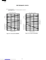
AH-S22AW2
AH-S25AW2
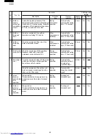
1
sec..
1
sec
0.6
sec.
1
sec.
1
sec.
1
sec.
1
sec.
1
sec.
0.6
sec.
1
sec.
1
sec.
1
sec.
1
sec.
1
sec.
1
sec.
1
sec.
1
sec.
1
sec.
0.6
sec.
0.6
sec.
1
sec.
0.6
sec.
1
sec.
0.6
sec.
100
80
60
40
20
0
-10
0
10
20
30
40
Resistance
Thermistor
Room temperature
Heat exchange
Color
Yellow
Orange
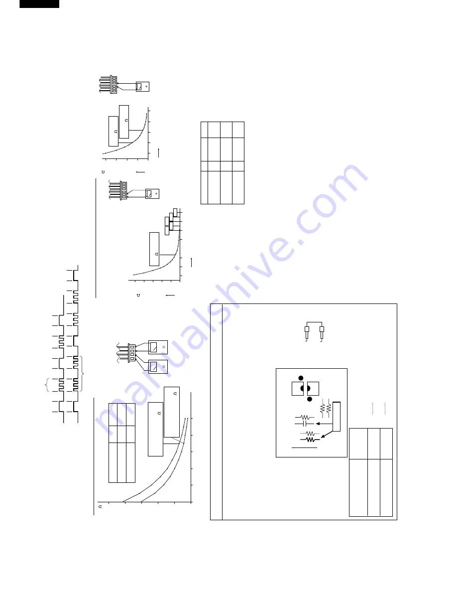
To measure the resistance, first remove
the soldering as shown at right.
Room temperature
thermistor TH1
Tester
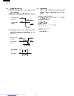
1 time
Compressor lock
Overheat of the compressor
2 times
ON
OFF
ON
OFF
Signal
CN4
CN4
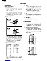
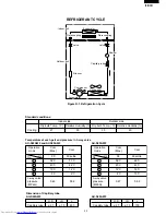
Figure 1 Temperature properties of indoor thermistors
500K
400K
300K
200K
100K
0
-20
0
20
60
80
100
120
3.06K
5.78K
4.17K
2.28K
1.72K
1
6
40K
30K
20K
10K
0
-20
0
20
60
40
1
6
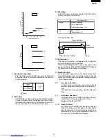
Figure 2 Temperature properties of outdoor thermistors
Connector
CN8
TH2 Heat exchange thermistor
TH3 Outdoor temp. thermistor
TH1 compressor thermistor
TH2,TH3
Connector
CN8
Temperature (
°
C)
Temperature (
°
C)
Tester
Tester
Thermistor
To measure the
resistance, first
remove the
connector from the
board.
Color
No.
Connector
Compressor
thermistor
Heat exchanger
pipe thermistor
Outdoor temp.
thermistor
TH1
TH2
TH3
No. 1 to 2
No. 3 to 4
Red
Orange
No. 5 to 6
Green
Microcomputer
terminal
Input
signal
To Outdoor control board
Adaptor
(C14 )
(GND)
(R17)
Pin No. 43
Pin No. 42
0
1
0 Low input
1 High input
K
Heat exchange thermistor
TH2 (orange)
25
°
C resistance 15 K
Room temperature
thermistor TH1 (yellow)
25
°
C resistance 10 K
25
°
C resistance
45 K
Resistance ( )
Resistance ( )
0
°
C resistance
14.5 K
25
°
C resistance
4.428 K
Heat exchange
thermistor TH2
Tester
4
1
Cautions when attaching or removing the board
When oper
ating only the outdoor unit (cooling 40 Hz fix
ed mode)
T
o mak
e
only the outdoor unit r
un in cooling mode
, shor
t the places mar
k
ed with
arro
ws belo
w with an adaptor
, and apply a v
oltage of 220 ~ 240
V A
C to 1
and N on the ter
minal board.
(A
v
oid oper
ating the outdoor unit alone f
or long per
iods of time
.)
PC1
PC2
R6
R5
R7
R16
R17
JP21
C14
Cool / 40Hz
3
4
1
2

