ENGLISH
GB-2
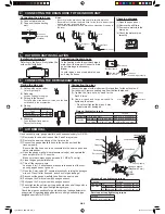
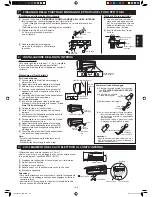
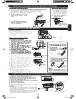
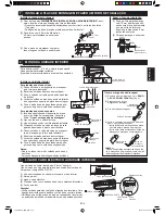
(1) Detache the front panel. Refer to the “
DE-
TACHING THE FRONT PANEL
(Page 4).”
(2) Unhook and pull out
the drain hose.
(3) Pull out the drain cap.
(4) Reconnect the drain hose and the drain
cap.
• Fully insert the drain hose until it stops
and hook on the projection.
• Insert a hexagon wrench into the drain
cap, and press it fully.
Caution:
After replacing, make sure that both the
drain hose and drain cap are
fi
rmly inserted.
N 2 4 5
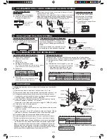
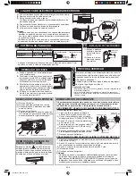
Mounting the indoor unit
For right side piping
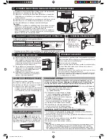
(1) Pass the pipes and the drain hose through the
piping hole.
(2) Hook the unit onto the mounting plate.
(3) Pull the connecting cable into the indoor unit.
(4) Push the unit and apply the bottom hooks to
the mounting plate's support.
(5) Pull the bottom of the unit to check that the unit
is
fi
xed in place.
For left side piping
(1) Reverse the positions of the drain hose and
drain cap. Refer to “
Exchange the drain
hose
”.
(2) Connect the pipes and connecting cable.
(3) Bind the pipes and connecting cable with tape.
(4) Set the them along the back of the unit, and
attach the piping holder.
(5) Pass the pipes, connecting cable and the drain
hose through the piping hole.
(6) Hook the unit onto the mounting plate.
(7) Push the unit and apply the bottom hooks to
the mounting plate's support.
(8) Pull the bottom of the unit to check that the unit
is
fi
xed in place.
Notes:
• Bend the pipes carefully as not to damage them.
• Lay the drain hose below the pipes.
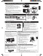
Use a copper cable.(Cross-section area: 2.0 mm
2
)
Use a cable which is not lighter than polychloroprene sheathed
fl
exible cord (Code designation 60245 IEC 57).
(1) Process the end of the connecting cable for the indoor side.
(2) Open the open panel.
(3) Connect the cable.
(4) Fix the cable with the cable cover and the short screw.
(5) Close the open panel.
Cautions:
• Be very careful not to confuse the terminal connections. Wrong
cabling may damage the internal control circuit.
• Be sure to connect the cable to match the markings on the
indoor unit’s terminal board and those of the outdoor unit.
Drain hose
MOUNTING PLATE
Taping
Wall
7
SHORT SCREW
8
CABLE COVER
Connecting cable
Earth wire
Terminal board
Drain cap
Drain hose
Hexagon wrench
Drain cap
Drain hose
Drain cap
8 mm
8 mm
40 mm
50 mm
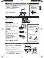
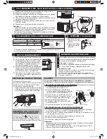
Making a piping hole
(1) Drill a piping hole with 70mm
diameter concrete drill or a hole
saw with a 5mm down ward
slant to the outside.
(2) Set the sleeve and caps.
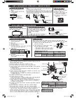
1 PLACING THE MOUNTING PLATE AND MAKING A PIPING HOLE
Installing the mounting plate
(1) Referring to the “
INSTALLATION DIMENSION OF INDOOR UNIT
”, mark the loca-
tion for the
fi
xing holes and the piping hole.
•
Recommended
fi
xing holes are marked in circle around the hole. (7 points)
• Make sure that the mounting plate is horizontally.
(2) Drill diameter 5.5 mm, depth 30 mm
holes and
fi
t the wall plug.
(3) Secure the mounting plate to the wall
with the long screws and check the
stiffness.
2 SETTING UP THE INDOOR UNIT
Piping route
For directions 1, 2 ,4 and 5, cut out the speci
fi
c zone
without leaving any sharp edge.
(Keep the cut-out plate for possible future use.)
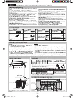
3 CONNECTING THE CABLE TO THE INDOOR UNIT
1
MOUNTING PLATE
3
LONG SCREW
Indoor
Outdoor
Cut with a saw.
Cap
5 mm
Sleeve
(Downward to
outdoor)
Plate
Cut the plate
along notch.
Plate
Plate
Hook
MOUNTING PLATE
Earth wire
Piping holder
Exchange the drain hose
1
2
3
4
5
30 mm
5.5 mm
2
WALL PLUG
Drain Hose
Pipes
Tape
04_A3AYAP9_2NR.indb GB-2
04_A3AYAP9_2NR.indb GB-2
2012-01-12 20:45:09
2012-01-12 20:45:09

