


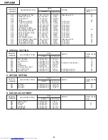


Sub-Tint Adjustment
1. Receive the half color bar signal.
•
RF INPUT (TU51)
2. Get into Y-Mute by R/C, or by setting the "V11" bus
data to "01".
3. Vary the "V02" bus data until the waveform becomes
as stated below.
Sub-Color Adjustment
1. Receive a good local channel.
2. Make sure the customer color control is set to center
position .
•
RF INPUT (TU51)
3. Enter the service mode and select service adjustment
"V03".
4. Adjust "V03" data value to obtain a normal color level.
Focus Adjustment
1. Receive a good local channel.
2. Adjust the FOCUS VR of the flyback transformer to
make the image as fine as possible.
C. C Display Position Adjustment
1. Receive the lion head pattern signal.
2. Select "EX2" to display the text box.
3. Adjust the "EX2" bus data to let the text box displayed
in the center.
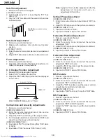
Vertical-Size and Linearity Adjustments
1. Receive a good local channel.
(SCREEN FORMAT 4:3)
2. Enter the service mode and select the service
adjustment "D03" for V-size.
3. Adjust the "D03" bus data to get the proper V-size.
4. For V-linearity adjustment, select data bus "D05" and
adjust to get the proper vertical linearity.
(SCREEN FORMAT 16:9)
5. Input data of "D22" to mines 38 step from "D03” data.
(V-SIZE)
6. Input data of "D24" same as "D05" data. (V-LIN)
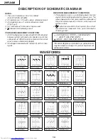
DISPLAY OF TEXT BOX
TEXT BOX
A
B
| A-B | / 2
SPEC INSPECTION:| A-B | / 2 <
= 5mm
B-AMP Base waveform in step
(TP47B)
LEVEL
Note: Aging for 10 min before adjustment. After the
adjustment of V-center and V-size, re-
adjustment for this V-line.
Vertical Phase Adjustment
(SCREEN FORMAT 4:3)
1. Enter the service mode and input data of “00h” on
"D01".
2. Adjust "D18" data value so that picture is centered.
(SCREEN FORMAT 16:9)
3. Input data of "00h" on "D20".
4. Input data of "D34" same as "D18" data.
Horizontal Position Adjustment
1. Receive a good local channel.
(SCREEN FORMAT 4:3)
2. Enter the service mode and select the service
adjustment "D02".
3. Adjust "D02" data value so that picture is centered.
(SCREEN FORMAT 16:9)
4. Input data of "D21" same as "D02" data.
Horizontal-Size Adjustment
1. Receive a good local channel.
(SCREEN FORMAT 4:3)
2. Enter the service mode and select the service
adjustment "D04" for H-size.
3. Adjust the "D04" bus data to get the proper H-size.
(SCREEN FORMAT 16:9)
4. Input data of "D23" same as "D04" data.
EW-Parabola
1. Receive a good local channel.
(SCREEN FORMAT 4:3)
2. Enter the service mode and select the service
adjustment "D07" for EW parabola.
3. Adjust the "D07" bus data to get the proper vertical
straight line for both left and right side.
(SCREEN FORMAT 16:9)
4. Input data of "D26" to mines 21 step from "D07" data.
EW-Trapezium
1. Receive a good local channel.
(SCREEN FORMAT 4:3)
2. Enter the service mode and select the service
adjustment "D08" for EW-Trapezium.
3. Adjust the "D08" bus data to get the best position
display.
(SCREEN FORMAT 16:9)
4. Input data of "D27" same as "D08" data.
29FL84M
10
Содержание 29FL84M
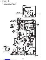
Страница 12: ...CHASSIS LAYOUT 29FL84M 12 ...
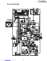
Страница 13: ...BLOCK DIAGRAM 29FL84M 13 ...
Страница 15: ...29FL84M 6 5 4 3 2 1 A B C D E F G H SCHEMATIC DIAGRAM CRT Unit 29FL84M 15 ...
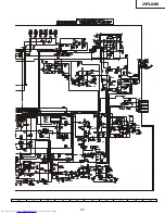
Страница 16: ...A B C D E F G H 10 9 8 7 6 5 4 3 2 1 SCHEMATIC DIAGRAM MAIN 1 Unit 29FL84M 16 ...
Страница 17: ...17 16 19 18 15 14 13 12 11 10 29FL84M 17 ...
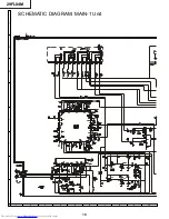
Страница 18: ...A B C D E F G H 10 9 8 7 6 5 4 3 2 1 SCHEMATIC DIAGRAM MAIN 1 Unit 29FL84M 18 ...
Страница 19: ...17 16 19 18 15 14 13 12 11 10 29FL84M 19 ...
Страница 20: ...A B C D E F G H 10 9 8 7 6 5 4 3 2 1 SCHEMATIC DIAGRAM MAIN 1 Unit 29FL84M 20 ...
Страница 21: ...17 16 19 18 15 14 13 12 11 10 29FL84M 21 ...
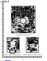
Страница 22: ...6 5 4 3 2 1 A B C D E F G H PWB A MAIN Unit Components Side 29FL84M 22 ...
Страница 23: ...6 5 4 3 2 1 A B C D E F G H PWB A MAIN Unit Chip Parts Side 29FL84M 23 ...


