11
28JF-73E
3.2 Operate in Service Mode and select location RED GAIN, GREEN GAIN and BLUE GAIN, to obtain colour
coordinates:
X=0.290 ± 0.015 Y=0.300 ± 0.015
To increase press volume-up button and to decrease press volume down button.
RED GAIN alter «X» coordinate.
GREEN GAIN alter «Y» coordinate.
BLUE GAIN alter «X» and «Y» coordinate.
3.3 Exit Service Mode and check colour coordinates «X» and «Y» at 3 and 100 NITS. It may be necessary to repeat
procedure 2 and 3 of Colour Adjustments.
R-G-B Cut Off and Gain Adjustments (alternative method).
In the event off a Colorimeter not being available, please follow the following procedures to obtain correct and Grey
scale settings (R-G-B Cut Off and Gain).
1. In the user menu, set the picture levels to the FACTORY settings (normalised).
2. Enter the Service Mode.
3. Adjust the G2 as in the previous page procedure.
4. Set the 50, 51, 52, 53, 54 and 55 NVM positions on page 00 from the original value to 80. Store each location by
pressing the stand-by button on the remote control.
5. Adjust grey scale as follows.
5.1 Select a grey scale signal, then set the Red Cut-off level to 32 and the Red-Gain to 50.
5.2 Leave the Red Cut-off and Gain as above and adjust Green and Blue Cut-off and Gain
to achieve correct grey scale tracking. As with all grey scale adjustments it will be neces-
sary to readjust the settings to achieve good tracking.
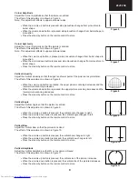
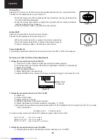
Note: The data to be adjusted is contained at the bottom right corner of the picture. See
Figure 15.
Changing NVM Data
To change the data contained within the Non Volatile Memory, it is necessary to first select the page the data is stored in,
then the position and finally to change the data itself. The procedure below outlines this process.
1. Press the channel up/down buttons and ALTER NVM PAG appears, use the volume up/down buttons to change this
data (it is shown in hexadecimal format).
2. Press the channel up button and ALTER NVM POS appears, use the volume up/down buttons to change this data (it is
shown in hexadecimal format).
3. Press the channel up button and ALTER NVM VAL appears, use the volume up/down buttons to change this data (it is
shown in hexadecimal format).
4. Once this data has been set, press the stand-by button to store.
5. If another NVM value has to be changed, use the channel down button to select the page or position and repeat as
necessary.
Note: DO NOT
change any NVM data, unless you have been advised to do so by a Sharp representative. If data is
incorrectly changed, serious damage may occur to the receiver.
Contrast Adjustments
Three types of contrast levels can be varied as listed below:
•
TELETEXT MIX MODE CONTRAST
•
TELETEXT CONTRAST
•
OSD CONTRAST
Use the volume up/down buttons to adjust to a suitable level, then. It is not necessary to press the stand-by button to store,
data are memorized by exiting the Service Mode.
Figure 15
BLUE GAIN XX
XX XX XX XX
XX XX XX XX


