background image

27U-S650

5

CIRCUIT PROTECTION

The receiver is protected by a 4.0A fuse (F701),
mounted on PWB-A, wired into one side of the AC
line input.

X-RADIATION PROTECTOR CIRCUIT TEST

After service has been performed on the horizontal
deflection system, high voltage system, B+ system,
test the X-Radiation protection circuit to ascertain
proper operation as follows:

1. Apply 120V AC using a variac transformer for accurate

input voltage.

2. Allow for warm up and adjust all customer controls

for normal picture and sound.

3. Receive a good local channel.
4. Connect a digital voltmeter to TP651 and make sure

that the voltmeter reads 13.2 ±0.7V.

5. Apply external 16.3V DC at TP651 by using an

external DC supply, TV must be shut off.

6. To reset the protector, unplug the AC cord and plug

the AC cord power on. Now make sure that normal
picture appears on the screen.

7. If the operation of the horizontal oscillator does not

stop in step 5, the circuit must be repaired before the
set is returned to the customer.

HIGH VOLTAGE CHECK

High voltage is not adjustable but must be checked
to verify that the receiver is operating within safe
and efficient design limitations as specified checks
should be as follows:

1. Connect an accurate high voltage meter between

ground and anode of picture tube.

2. Operate receiver for at least 15 minutes at 120V AC

line voltage, with a strong air signal or a properly tuned
in test signal.

3. Enter the service mode and select the service

adjustment "V18" and Bus data "01" (Y-mute on, CRT
Cut Off).

4. The voltage should be approximately 29.0kV (at zero

beam).
If a correct reading cannot be obtained, check circuitry
for malfunctioning components.  After the voltage test,
make Y-mute off to the normal mode.

INSTALLATION AND SERVICE INSTRUCTIONS

Note:

(1) When performing any adjustments to resistor controls and transformers use non-metallic

screwdrivers or TV alignment tools.

(2) Before performing adjustments, the TV set must be on at least 15 minutes.

Содержание 27U-S650

Страница 1: ...NG BOARD ASSEMBLIES 23 REPLACEMENT PARTS LIST 28 PACKING OF THE SET 39 CONTENTS SPEAKER SIZE 9 x 5 cm oval 2 pcs VOICE COIL IMPEDANCE 8 ohm at 400 Hz ANTENNA INPUT IMPEDANCE VHF UHF 75 ohm Unbalanced TUNING RANGES VHF Channels 2 thru 13 UHF Channels 14 thru 69 CATV Channels 1 thru 125 EIA Channel Plan U S A POWER INPUT 120V AC 60 Hz POWER RATING 126W PICTURE SIZE 2 187cm2 339sq inch CONVERGENCE Ma...

Страница 2: ...igh voltage with a meter to be certain that the high voltage does not exceed the specified value and that it is regulating correctly 5 Do not use a picture tube other than that specified or make unrecommended circuit modifications to the high voltage circuitry 6 When trouble shooting and taking test measurements on a receiver with excessive high voltage avoid being unnecessarily close to the recei...

Страница 3: ...y networks mechanical insulators etc 3 To be sure that no shock hazard exists check for leakage current in the following manner Plug the AC cord directly into a 120 volt AC outlet Do not use an isolation transformer for this test Using two clip leads connect a 1 5k ohm 10 watt resistor paralleled by a 0 15µF capacitor in series with all exposed metal cabinet parts and a known earth ground such as ...

Страница 4: ...nverter Box requires an enter command after selecting channels when using the REMOTE KEYPAD button CHANNEL UP DOWN Moves the mark of the MENU screens MUTE Press Mutes sound Press again Restores sound CLOSED CAPTION appears when sound is muted PIP FUNCTION With the VIDEO inputs you can watch two pictures at the same time POWER Press On Press again Off REMOTE KEYPAD Accesses any channel from keypad ...

Страница 5: ...izontal oscillator does not stop in step 5 the circuit must be repaired before the set is returned to the customer HIGH VOLTAGE CHECK High voltage is not adjustable but must be checked to verify that the receiver is operating within safe and efficient design limitations as specified checks should be as follows 1 Connect an accurate high voltage meter between ground and anode of picture tube 2 Oper...

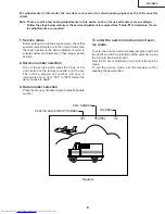
Страница 6: ...e in their proper reset position 2 Service number selection Once in the service mode press the Ch up or Ch down button on the remote controller or at the set The service adjustment number will vary in increments of one from V01 to P08 Select the item you wish to adjust 3 Data number selection Press the Vol up or Vol down button to adjust the data number To enter the service mode and exit serv ice ...

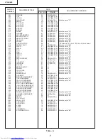
Страница 7: ...et to 01 V31 RGB CONTRAST 20 0 63 00h 3Fh Must be set to 31 V32 Y DL 02 0 7 00h 07h Must be set to 02 V33 Y DL INPUT 01 0 7 00h 07h Must be set to 01 V34 VSM GAIN 07 0 7 00h 07h Must be set to 07 V35 N COMB 01 0 1 Must be set to 01 V36 BPF TOF INPUT 00 0 1 Must be set to 01 V37 CORING 00 0 1 Must be set to 00 V38 VSM PHASE 00 0 1 Must be set to 00 V39 COLOR γ 00 0 1 Must be set to 01 V40 SHARP INP...

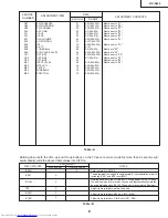
Страница 8: ...CO 24 0 63 00h 3Fh M03 FILTER 1F 0 63 00h 3Fh M04 WIDEBAND 18 0 63 00h 3Fh M05 SPECTRAL 10 0 63 00h 3Fh SERVICE NUMBER DATA ADJUSTMENT ITEM INITIAL VALUE RANGE ADJUSTMENT CONTENTS Table A NECESSARY UNNECESSARY ADJUSTMENT PART REPLACED IC2001 IC201 X Data is stored in IC2102 The adjustment is needed to compensate for characteristics of parts including IC201 and MTS level M01 Holding down both the V...

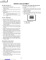
Страница 9: ...eset data to 00 Select the service adjustment V03 and reset data to obtain normal color level 7 For component input the data value of V46 red V47 green and V48 blue is adjusted to follow the data value of V06 V07 and V08 respectively 8 Reset the master screen control to obtain normal brightness range White Balance Adjustment 1 Receive a good local channel 2 Enter the service mode and select the se...

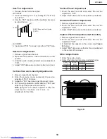
Страница 10: ...justment select data bus D05 and adjust to get the proper vertical linearity Note Aging for 10 min before adjustment After the adjustment of V phase and V size re adjustment for this V line Vertical Phase Adjustment 1 Enter the service mode and select the service adjustment D01 2 Adjust D01 data value so that picture is centered Horizontal Position Adjustment 1 Receive a good local channel 2 Enter...

Страница 11: ...owing composite signal Monaural signal 400Hz 100 modulation 2 Connect the rms voltmeter to pin 39 of IC3001 3 Enter the service mode and select the service adjustment M01 and set to 09 4 Enter the service mode and select the service adjustment EX4 5 Adjust the data so that the rms voltmeter reads 490 10 mVrms MTS VCO Adjustment 1 Keep the unit in no signal state 2 Connect the frequency counter to ...

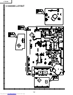
Страница 12: ...12 6 5 4 3 2 1 A B C D E F G H 27U S650 CHASSIS LAYOUT ...

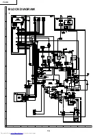
Страница 13: ...13 6 5 4 3 2 1 A B C D E F G H 27U S650 BLOCK DIAGRAM ...

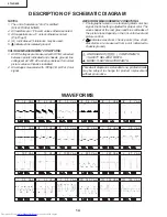
Страница 14: ...C voltages are measured with DVM connected between points indicated and chassis ground line voltage set at 120V AC and all controls set for normal picture unless otherwise indicated 2 All voltages measured with 1000µ V B W or Color signal WAVEFORM MEASUREMENT CONDITIONS 1 Photographs taken on a standard gated color bar signal the tint setting adjusted for proper color The wave shapes at the red gr...

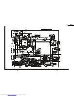
Страница 15: ...16 27U S650 15 12 11 10 9 8 7 6 5 4 3 2 1 A B C D E F G H ...

Страница 16: ...16 18 27U S650 17 12 11 10 9 8 7 6 5 4 3 2 1 A B C D E F G H ...

Страница 17: ...20 27U S650 19 12 11 10 9 8 7 6 5 4 3 2 1 A B C D E F G H ...

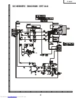
Страница 18: ...21 27U S650 6 5 4 3 2 1 A B C D E F G H SCHEMATIC DIAGRAM CRT Unit ...

Страница 19: ...22 6 5 4 3 2 1 A B C D E F G H 27U S650 DIAGRAM MTS MODULE Unit ...

Страница 20: ...27U S650 6 5 4 3 2 1 A B C D E F G H 23 PRINTED WIRING BOARD ASSEMBLIES PWB A MAIN Unit Wiring Side ...

Страница 21: ...27U S650 6 5 4 3 2 1 A B C D E F G H 24 PWB A MAIN Unit Chip Parts Side ...

Страница 22: ...25 6 5 4 3 2 1 A B C D E F G H 27U S650 PWB C AV Unit Wiring Side PWB C AV Unit Chip parts Side ...

Страница 23: ...26 6 5 4 3 2 1 A B C D E F G H 27U S650 PWB S MTS MODULE Unit Wiring Side PWB S MTS MODULE Unit Chip Parts Side ...

Страница 24: ...27 6 5 4 3 2 1 A B C D E F G H 27U S650 PWB B CRT Unit Wiring Side ...

Страница 25: ...02GJKZ X Wire Holder x6 AC MSPRT0002MEZZ Spring AE å QEARC2702MEZZ Grounding Strap AD PRINTED WIRING BOARD ASSEMBLIES NOT REPLACEMENT ITEM PWB A DUNTKA526WEE8 MAIN Unit PWB B DUNTKA527WEB9 CRT Unit PWB C DUNTKA602WEA0 AV Unit PWB S DUNTKB224WEA2 MTS MODULE Unit PWB A DUNTKA526WEE8 MAIN UNIT TUNER NOTE THE PARTS HERES SHOWN ARE SUPPLIED AS AN ASSEMBLY BUT NOT INDEPENDENTLY å TU51 VTUVTST5UF740 X Tu...

Страница 26: ...er Diode 9 1V AA D2402 RH EX0619GEZZ J Zener Diode 6 2V AA D2403 RH EX0619GEZZ J Zener Diode 6 2V AA å VA701 RH VX0019CEZZ J Varistor AC or RH VX0048CEZZ or RH VX0035CEZZ PACKAGED CIRCUITS å PR702 RMPTP0092CEZZ J Packaged Circuit AH X801 RCRSAA011WJZZ X Crystal AG or RCRSB0278CEZZ FILTERS AND COILS CF202 RFiLC0447CEZZ J Ceramic Filter AD CF403 RFiLC0446CEZZ J Ceramic Filter AD CF2040 RFiLA0099CEZZ...

Страница 27: ...00V Ceamic AC C703 RC KZ0029CEZZ J 0 01 500V Ceramic AC å C705 RC EZ0800CEZZ J 560 200V EL AQ C706 RC KZ021SCEZZ J 3300p 2kV Ceramic AE C710 RC KZ0040CEZZ J Capacitor AD C712 VCKYCY1HB103K J 0 01 50V Ceramic AA C717 VCKYPA2HB472K J 4700p 500V Ceramic AB C722 VCQYTA1HM104J J 0 1 50V Mylar AA å C723 RC EZ0724CEZZ J 100 160V EL AG å C725 RC EZ0810CEZZ J 330 160V EL AH C726 VCKYPH3DB561K J 560p 2kV Ce...

Страница 28: ...x AA R211 VRS CY1JF331J J 330 1 16W M Ox AA R212 VRS CY1JF000J J 00 1 16W M Ox AA R215 VRS CY1JF222J J 2 2k 1 16W M Ox AA R217 VRS CY1JF102J J 1k 1 16W M Ox AA R219 VRS CY1JF102J J 1k 1 16W M Ox AA R220 VRS CY1JF392J J 3 9k 1 16W M Ox AA R225 VRD RA2BE680J J 68 1 8W Carbon AA R226 VRD RA2BE101J J 100 1 8W Carbon AB R227 VRS CY1JF333J J 33k 1 16W M Ox AA R228 VRS CY1JF102J J 1k 1 16W M Ox AA R229 V...

Страница 29: ... 2W Carbon AA å R737 VRN RL3DBR56J 0 56 2W M Film R744 VRS CY1JF272J J 2 7k 1 16W M Ox AA R745 VRS CY1JF272J J 2 7k 1 16W M Ox AA R746 VRS CY1JF103J J 10k 1 16W M Ox AA R747 VRS CY1JF103J J 10k 1 16W M Ox AA å R750 RR DZ0049CEZZ J 3 9M 1 2W Solid AB or RR DZ0048CEZZ R751 VRS CY1JF473J J 47k 1 16W M Ox AA R766 VRS CY1JF333J J 33k 1 16W M Ox AA R767 VRS CY1JF273J J 27k 1 16W M Ox AA R768 VRS CY1JF33...

Страница 30: ...VRS CY1JF101J J 100 1 16W M Ox AA R2201 VRS CY1JF222J J 2 2k 1 16W M Ox AA R2202 VRS CY1JF103J J 10k 1 16W M Ox AA R2203 VRS CY1JF184J J 180k 1 16W M Ox AA R2211 VRS CY1JF222J J 2 2k 1 16W M Ox AA R2212 VRS CY1JF682J J 6 8k 1 16W M Ox AA R2213 VRS CY1JF333J J 33k 1 16W M Ox AA R2401 VRS CY1JF101J J 100 1 16W M Ox AA R2402 VRD RA2BE101J J 100 1 8W Carbon AB R2403 VRD RA2BE101J J 100 1 8W Carbon AB ...

Страница 31: ...ode AB D1503 VHD1SS119 1 J Diode AB D1506 RH DX0487CEZZ J Diode AC D1507 RH DX0487CEZZ J Diode AC D1510 VHD1SS119 1 J Diode AB CAPACITORS EL Electrolytic C850 VCFYSB2EB823J J 0 082 250V Mylar AD C851 RC KZ018JCEZZ J 0 01 AC250V Ceramic AC or RC KZ015JCEZZ C852 VCEA0A1CW227M J 220 16V EL AC C853 VCFYFA1HA224J J 0 22 50V Mylar AB C854 VCEA0A1CW227M J 220 16V EL AC C855 VCEA0A2EW106M J 10 250V EL AD ...

Страница 32: ...YBN AC P860 QPLGN0841CEZZ J Plug 8 pin GBN AB P861 QPLGN0241CEZZ J Plug 2 pin PU AA SC850 QSOCV0937CEZZ J CRT Socket AL RDA850PRDAR0248PEFW R Heat Sink for IC850 AF RDA1506 PRDAR5072CEFW J Heat Sink for Q1506 AC RDA1507 PRDAR5072CEFW J Heat Sink for Q1507 AC LX BZ3100CEFD J Screw AA PWB B DUNTKA527WEB9 CRT UNIT PWB C DUNTKA602WEA0 AV UNIT INTEGRATED CIRCUITS IC1401 VHiTC90A53F 1 X I C AV IC1900 VH...

Страница 33: ...CY1JF000J J 0 1 16W M Ox AA RJ19 VRS CY1JF000J J 0 1 16W M Ox AA RJ20 VRS CY1JF000J J 0 1 16W M Ox AA RJ21 VRS CY1JF000J J 0 1 16W M Ox AA RJ22 VRS CY1JF000J J 0 1 16W M Ox AA RJ23 VRS CY1JF000J J 0 1 16W M Ox AA R1401 VRS CY1JF101J J 100 1 16W M Ox AA R1402 VRS CY1JF681J J 680 1 16W M Ox AA R1403 VRS CY1JF332J J 3 3k 1 16W M Ox AA R1404 VRS CY1JF102J J 1k 1 16W M Ox AA R1405 VRS CY1JF471J J 470 1...

Страница 34: ...S AC QCNW 0165GJZZ Connecting Cord EJ AC QCNW 0167GJZZ Connecting Cord AC QCNW A381WJZZ X Connecting Cord TA AG QCNW A382WJZZ X Connecting Cord SG1 AF QCNW A383WJZZ X IF Cable AH QCNW A476WJZZ Connecting Cord AC TCAUH3045GJZZ Caution Card AD TLABM0002GJZZ X Model Label AB TLABZ0152GJZZ X Feature Label AD XTASD30P12000 J Screw AA XTASD30P12000 J Screw x4 AA XTASD40P20000 J Screw AA SUPPLIED ACCESSO...

Страница 35: ...Bag TLABZA058WJZZ Carton Label CABINET PARTS CABINET PARTS LOCATION 1 CCABAA060WEH0 Front Cabinet Ass y BD 1 1 Not Available Front Cabinet 1 2 GCOVA0121GJSA RC LED Cover AC 1 3 GDORFA004WJSA Door AC 1 4 GCOVA0116GJKA Door Cover AC 1 5 HBDGB1009MESB Badge SHARP AG 1 6 HiNDP0105GJKZ Indication Plate AB 1 7 JBTN 0138GJKB Button Power AF 1 8 JBTN 0139GJSB Button CH Up Down AF VOL Up Down Menu 2 GCABBA...

Страница 36: ...acement items FRONT Buffer Material Polyethylene Sheet Polyethylene Bag Operation Manual Infrared R C Unit Batteries REAR Use tape to fix the top side of packing case Use 12 staples to fix the bottom side of packing case PACKING OF THE SET ...

Страница 37: ...rieval system or transmitted in any form or by any means electronic mechanical photocopying recording or otherwise without prior written permission of the publisher SHARP ELECTRONICA MEXICO S A DE C V Blvd SHARPNo 3510ParqueIndustrial Rosarito Playas de Rosarito B C 22710 D SEM P SEMEX TQ0000 S June 2002 Printed in Japan MI KG ...

Отзывы: