S o l d e r
I
U n s o l d e r h e r e
block
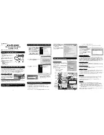
Figure l-69.
Unsolder the leads
from the
motor.
2. Unlock the
and right catches
of the cam
switch off the loading block. Take out the cam
switch and loading block
PWB (See Figure
Tally marks
b l o c k
P u l l u p t h e c a m
c a t c h e s R e m o v e t h e c a m
2
t o g e t h e r
the
b l o c k
C a t c h e s o f c a m
Figure
3. Take out the loading belt
4. Pry up the back end of the loading motor with a
screw driver or the like as Figure
and take
out the motor.
M o t o r l a b e l
I
3
or the
h e r e P r y u p
t h e
e n d o f the
m o t o r a n d
t a k e
m o t o r
Figure
Reassembly
1.
Remove the loading motor, and mount a new
loading motor as in Figure l-72.
2. Place the loading motor so that its label is visible
as shown in Figure l-72. Make sure that the
screw hole at the motor shaft, protuberance on
the loading block, and the motor’s back end
marked with the arrow are mated with each
other.
Label
Figure l-72.
Note:
When press-fitting
the loading
motor pulley, keep the pressure
less than 5 kg, and the gap
between the motor and pulley
should be
mm.
Figure l-73.
3. Set the loading block PWB and the cam switch in
position.
4. Resolder the leads to the loading motor.
5. Finally place the loading block (See page
6. Attach the loading belt.
Removal
Remove the ring
2. Remove the half-loading drive lever
3. Remove the ring
4. Remove the pinch roller lever
5. Pull out the master cam upward
Pinch roller lever
P i n c h
l e v e l
cam follower
B o t t o m
of
m a s t e r
Enters the outermost
cam groove
cam follower
l e v e r t o t h e
Slow brake lever cam follower
Figure
Содержание 14VT10X1
Страница 66: ...OVERALL BLOCK DIAGRAM 6 9 ...
Страница 67: ...I 7 I a I 9 I 10 I 11 I 12 1 7 0 ...
Страница 68: ...SERVO PROCESS BLOCK DIAGRAM I SERIAL REF CBOl 43PIN AH IF 1 DECODER PB ON A 0 C G H 6 1 1 2 I 3 I 4 I 5 I i ...
Страница 69: ...T 1 i r I 1 I i L I I 7 I a I 9 I 10 I 11 I 12 1 72 ...
Страница 70: ...I I_ J I I I I 1 y I ...
Страница 71: ...u ...
Страница 80: ...N w P m 0 u 1 FC r i z I 3 I i r i nna AMP i I ...
Страница 83: ... t m m I 7 I 8 I 9 I 10 I 11 I 12 1 8 8 l _ ...
Страница 84: ...J BLOCK DIAGRAM __ _ a I l vA 8 C D E F G 1 H I e 1 a B h I VIDEO Cl 1 I 2 I 3 I 4 I 5 I 6 I 8 7 ...
Страница 91: ...CRT CRT CRT TTin J Ll T 0 78Vp P 0 O 78Vp p HI 78Vp P U 0 ...
Страница 92: ...OVERALL DIAGRAM HEAD AMP PWB J SERVOSYSCON PM K cunx3 LBoT AUDIO UNIT VCR MAIN Y C UNIT PWR c oum l Z TusO ...
Страница 93: ...VCR POWER PWB P RDENCWBDGELZ CRT PWB PWB H ...
Страница 95: ......
Страница 97: ...I AUDIO MODULE WJNTK0677GEZZ F3626GE OPERATION DUNTK3627HE50 F3627GE I ...
Страница 98: ... H ...
Страница 99: ...I _ ...
Страница 101: ...J EL s I or VHIXRA7252 I FM EO I 7 I 8 I 9 I 1 0 I 11 I 1 2 I 1 0 4 ...
Страница 102: ...VCR POWER CIRCUIT 105 ...
Страница 103: ...I 7 I a I 9 I 10 I 11 I 12 I 106 ...
Страница 105: ...INFRARED REMOTE CONTROL CIRCUIT I I I I I 1 1 I 2 I 3 I 4 I 5 I 6 1 108 ...
Страница 106: ...1 W MOTHER CRT CIRCUIT 1 I 2 I 3 I 4 I 5 I 6 I l VOLTAGE MEASUREMENT MODE PB Parentheses REC Without Parentheses ...
Страница 107: ...0 P cc I I I ...
Страница 108: ... N w e VI 0 I l 1 ma c I s m A t T I I I I I I I I I I I I I I Ii I x 2 N I rNllllll I ...
Страница 109: ...m M M I 7 I 8 I 112 8 1 t _I 11 I 12 1 ...
Страница 110: ...2 W 1 0007 OTC 14EK ...
Страница 111: ...I I c I n I In I 0 3 I 0 b II m 2 2 m HF H NNT w O TLN O IGC O en O Zb ...
Страница 112: ...N w P Gl 07 Ll I I t I n I m I 0 I 0 I m I D I m ...
Страница 113: ...C A B C D E F G H YIC PWB VCR POWER PWB 1 I 2 I 3 I 4 I 5 I 6 I ...
Страница 114: ...I I I 0 I m I m I 0 I n I m I D I A SBIIO C H c j u ...
Страница 115: ...9 A B C D E F G H VCR AUDIO PWB CRT PWB TV CONTROL 2 PWB TV CONTROL 1 PWB 1 I 2 I 3 I 4 I 5 I 6 I 118 ...
Страница 116: ...TV MOTHER PWB 1 I 2 I 3 I 4 I 5 I 6 I 119 ...
Страница 117: ...TIMER PWB 1 I 2 I 3 I 4 5 I 6 1 120 ...
Страница 134: ... A B E F G ...
Страница 135: ...CASSElTE HOUSING CONTROL PARTS 3 1 7 I 9 3 wf 345 1 I 2 I 3 I 5 I 5 I 6 1 138 ...
Страница 136: ... A B C D E F G l 4 TV SECTION MECHANICAL PARTS 1 I 2 I 3 I 4 I 5 I 6 I 139 ...
Страница 137: ...VCR SECTION MECHANICAL PARTS 1 I 2 1 3 I 4 I 5 I 6 I ...


