background image

17

13N-M100/150
CN13M10

16

12

11

10

9

8

7

6

5

4

3

2

1

A

B

C

D

E

F

G

H

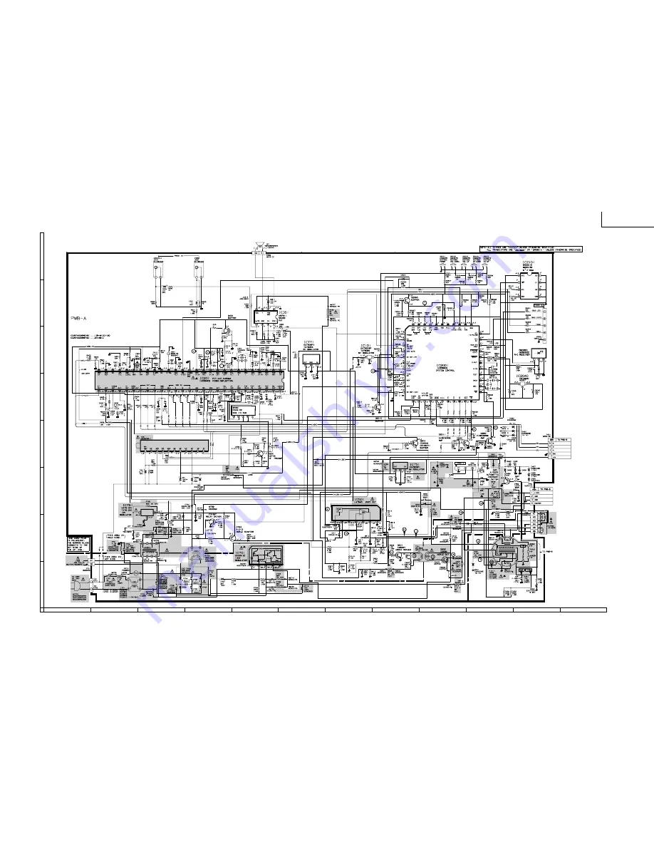
SCHEMATIC DIAGRAM: MAIN Unit

Содержание 13N-M100

Страница 1: ...nt has been published to be used for after sales service only The contents are subject to change without notice MODELS POWER INPUT 120 V AC 60 Hz POWER RATING 69 W PICTURE SIZE 580cm2 89 8sq inch CONVERGENCE Magnetic SWEEP DEFLECTION Magnetic FOCUS Hi Bi Potential Electrostatic INTERMEDIATE FREQUENCIES Picture IF Carrier Frequency 45 75 MHz Sound IF Carrier Frequency 41 25 MHz Color Sub Carrier Fr...

Страница 2: ...tion of this meter should be checked periodically 3 High voltage should always be kept at the rated value no higher Operation at higher voltages may cause a failure of the picture tube or high voltage circuitry and also under certain conditions may produce radiation in exceeding of desirable levels 4 When the high voltage regulator is operating properly there is no possibility of an X radiation pr...

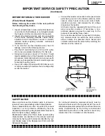
Страница 3: ...ity networks mechanical insulators and etc 3 To be sure that no shock hazard exists check for leakage current in the following manner Plug the AC cord directly into a 120 volt AC outlet Do not use an isolation transformer for this test Using two clip leads connect a 1 5k ohm 10 watt resistor paralleled by a 0 15µF capacitor in series with all exposed metal cabinet parts and a known earth ground su...

Страница 4: ...r le tube image qu en porant des lunettes incassables et qu après avoir déchargé totalement la haute tension LIMITES DES RADIATIONS X ET DE LA HAUTE TENSION 1 Tout le personnel réparateur doit être instruit des instructions et procédés relatifs aux radiations X Le tube image seule source de rayons X dons les téleviseurs transistorisés n émet pourtant pas de rayons mesurables si la haute tension es...

Страница 5: ...lateurs mécaniques etc 3 S assurer qu il n y ait pas de danger d électrocution en vérifiant la fuite de courant de la facon suivante Brancher le cordon d alimentation directem ent à une prise de courant de 120V Ne pas utiliser de transformateur d isolation pour cet essai A l aide de deux fils à pinces brancher une résistance de 1 5 kΩ 10 watts en parallèle avec un condensateur de 0 15µF en série a...

Страница 6: ...displays receiving channel when in Closed Caption mode Basic Remote Control Functions Front Panel CHANNEL UP DOWN MENU Selects next higher channel Selects next lower channel Press both at the same time to access the MAIN MENU screen SENSOR AREA FOR REMOTE CONTROL VOLUME UP DOWN Increases sound Decreases sound POWER Press On Press again Off VIDEO AUDIO IN TERMINALS POWER Press On Press again Off RE...

Страница 7: ...e operation of the horizontal oscillator does not stop in step 5 the circuit must be repaired before the set is returned to the customer HIGH VOLTAGE CHECK High voltage is not adjustable but must be checked to verify that the receiver is operating within safe and efficient design limitations as specified checks should be as follows 1 Connect an accurate high voltage meter between ground and anode ...

Страница 8: ...e normal mode Use the reset function in the video adjustment menu to ensure customer control are in their proper reset position 2 Service number selection In the service mode you will see the window screen as window 1 There are 3 adjustment categories 2DEF 3SIGNAL 4FIX VALUE as show in Figure A Press CH UP DOWN button for selection and enter by VOL UP or VOL DOWN Press CH UP DOWN button to select ...

Страница 9: ...06 SERVICE POSITION ADJUST ITEM DATA RANGE INITIAL VALUE Hex Must be B0 for 13N M100 150 A0 for CN13M10 Table A Below are the ranges and initial values for each adjustment and in each categories DEF D01 H PHASE 00 1F 0C D02 V SIZE 00 7F 40 D03 V POSITION 00 3F 20 Must be 20 D04 CC POSITION 00 FF 1A D05 V LINEARITY 00 1F 10 Must be 12 D06 V S CORRECTION 00 1F 10 Must be 0F SERVICE POSITION ADJUST I...

Страница 10: ... more than 2 seconds will automatically write the above initial values into IC2101 Table D The adjustment is needed to compensate for characteristics of parts including IC201 Holding down both the Vol up Ch down buttons on the TV set in the service mode for more than 2 seconds will automatically write the above initial values into IC2101 X X ADJUSTMENT NECESSARY UNNECESSARY PART REPLACED NOTES ...

Страница 11: ...channel 2 Enter the service mode signal category and select the service adjustment S01 3 Set the data value to point where no noise or beat appears 4 Select another channel to confirm that no noise or beat appears Note You have to exit the service mode first to select another channel Video Level TV Det Video Level Adjustment 1 Receive a good local channel 2 Enter the service mode signal category a...

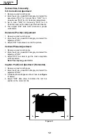
Страница 12: ...ceive a good local channel 2 Enter the service mode DEF category and select the adjustment D01 3 Adjust D01 data value to center the picture Vertical Phase Adjustment 1 Receive a good local channel 2 Enter the service mode DEF category and select the adjustment D03 3 Adjust D03 bus data to get the most acceptable vertical position Note The step range is 20 10 Caption Position Adjustment Horizontal...

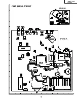
Страница 13: ...13 13N M100 150 CN13M10 6 5 4 3 2 1 A B C D E F G H CHASSIS LAYOUT PWB A PWB B ...

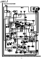
Страница 14: ...14 13N M100 150 CN13M10 BLOCK DIAGRAM 6 5 4 3 2 1 A B C D E F G H SYNC SEP OUT 22 ...

Страница 15: ...d 2 All voltages measured with 1000µ V B W or Color signal WAVEFORM MEASUREMENT CONDITIONS 1 Photographs taken on a standard gated color bar signal the tint setting adjusted for proper color The wave shapes at the red green and blue cathodes of the picture tube depend on the tint color level and picture control 2 indicates waveform check points See chart waveforms are measured from point indicated...

Страница 16: ...17 13N M100 150 CN13M10 16 12 11 10 9 8 7 6 5 4 3 2 1 A B C D E F G H SCHEMATIC DIAGRAM MAIN Unit ...

Страница 17: ...18 13N M100 150 CN13M10 SCHEMATIC DIAGRAM CRT Unit 6 5 4 3 2 1 A B C D E F G H ...

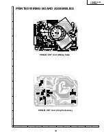
Страница 18: ...19 13N M100 150 CN13M10 PRINTED WIRING BOARD ASSEMBLIES 6 5 4 3 2 1 A B C D E F G H PWB B CRT Unit Chip Parts Side PWB B CRT Unit Wiring Side ...

Страница 19: ...20 13N M100 150 CN13M10 PWB A MAIN Unit Wiring Side 6 5 4 3 2 1 A B C D E F G H ...

Страница 20: ...21 13N M100 150 CN13M10 PWB A MAIN Unit Chip Parts Side 6 5 4 3 2 1 A B C D E F G H ...

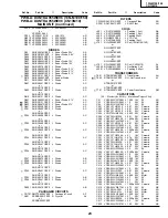
Страница 21: ...T COMMANDER LES PIECES DE RECHANGE Pour que votre commande soit rapidement et correctement remplie veuillez fournir les renseignements suivants 1 NUMERO DU MODELE 2 NO DE REF 3 NO DE PIECE 4 DESCRIPTION in CANADA Contact SHARP Electronics of Conada Limited Phone 416 890 2100 MARQUE SECTION LIVRAISON DES PIECES DE RECHANGE MARQUE PIECES RELATIVE AUX RAYONS X çå V101 VB370BVBK1S S R CRT DY601 H0143P...

Страница 22: ...eaking 22µH AB L204 RCiLi0632CEZZ J VCO Coil AE L301 VP XF150K0000 J Peaking 15µH AB å L701 RCiLF0069PEZZ R Coil 13N M100 150 AG or RCiLF0037PEZZ or RCiLF0078PEZZ or RCiLF0029PEZZ or RCiLF0090CEZZ å L701 RCiLF0090CEZZ R Coil CN13M10 AL L2040 RCiLB0131CEZZ J Oscillation Coil AE L2201 VP XFR82K0000 J Peaking 0 82µH AB TRANSFORMERS å T601 RTRNZ0168CEZZ J Transformer AH çå T602 RTRNF0156PEZZ R H Out T...

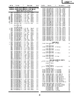
Страница 23: ... 10W M Film AA RJ29 VRN MD2AL000J J 0 1 10W M Film AA å R53 VRS VV3LB223J J 22k 3W M Ox AB R54 VRN MD2AL101J J 100 1 10W M Film AA R55 VRN MD2AL101J J 100 1 10W M Film AA R56 VRN MD2AL823J J 82k 1 10W M Film AA R57 VRD RA2BE563J J 56k 1 8W Carbon AA R201 VRN MD2AL221J J 220 1 10W M Film AA R202 VRN MD2AL122J J 1 2k 1 10W M Film AA R203 VRD RA2BE682J J 6 8k 1 8W Carbon AA R204 VRN MD2AL270J J 27 1 ...

Страница 24: ...J J 680k 1 10W M Film AA R2040 VRD RA2BE102J J 1 0k 1 8W Carbon AA R2041 VRN MD2AL333J J 33k 1 10W M Film AA R2042 VRD RA2BE101J J 100 1 8W Carbon AB R2043 VRD RA2BE101J J 100 1 8W Carbon AB R2044 VRN MD2AL683J J 68k 1 10W M Film AA R2045 VRN MD2AL101J J 100 1 10W M Film AA R2047 VRN MD2AL221J J 220 1 10W M Film AA PWB A DUNTKA055WEV6 13N M100 150 PWB A DUNTKA055WEV8 CN13M10 MAIN UNIT Continued R2...

Страница 25: ...336M J 33 16V EL AB RESISTORS M Ox Metal Oxide M Film Metal Film R852 VRD RA2BE221J J 220 1 8W Carbon AA R853 VRN MD2AL121J J 120 1 10W M Film AA å R857 VRS VV3AB123J J 12k 1W M Ox AA R858 VRD RM2HD332J J 3 3k 1 2W Carbon AA R860 VRD RA2BE221J J 220 1 8W Carbon AA R861 VRN MD2AL121J J 120 1 10W M Film AA å R865 VRS VV3AB123J J 12k 1W M Ox AA R866 VRD RM2HD332J J 3 3k 1 2W Carbon AA R867 VRN MD2AL4...

Страница 26: ...27 13N M100 150 CN13M10 PACKING OF THE SET REAR Use tapes to fix the packing case Packing Case FRONT Buffer Material Wrapping Paper Polyethylene Bag Operation Manual Batteries MARK Not Replacement Items ...

Страница 27: ...ced stored in a retrieval system or transmitted in any form or by any means electronic mechanical photocopying recording or otherwise without prior written permission of the publisher SHARP CORPORATION AV Systems Group Quality Reliability Control Center Yaita Tochigi 329 2193 Japan TQ0823 S Feb 2000 Printed in Japan MI KG ...

Отзывы: