background image

PAGE 17

PAGE 16

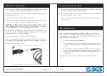
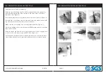
1.  Rotate the bearing seat so that the aperture faces the tab of the set 

plate.

2.  Push the set plate forward so that the tab enters the aperture in the 

bearing seat. The bearing seat will be held static.

3.  Screw the sanding pad onto the bearing seat by hand and ensure it is 

fully tightened. Release the set plate tab before the tool can be used.

FITTING THE SANDING SHEET

4.  Peel off the back of the self adhesive sanding sheet and stick it to the 

backing pad. Take care that it is positioned centrally.

5.  IMPORTANT: Only use sanding sheets designed for use with this type 

of 150mm dia sanding pad.

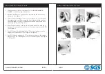
SANDER - INSTALLING THE PAD

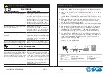
1.  Squeeze the trigger against the body of the tool to start the sander 

and control the speed. Evaluate the speed and adjust as follows.

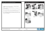
2.  Adjust the operating speed by twisting the speed control shown. The 

speed of rotation is shown by the arrow embossed on the tool body 
(anti-clockwise will increase the sanding speed.)

3.  To begin work, rest the disc pad on the workpiece and start the 

sander. Let the tool do the work. The actual weight of the machine is 
normally sufficient for efficient sanding. Do not put additional pres-
sure on the machine, which would only slow down the speed of the 
pad, reducing efficiency and placing an additional burden on the mo-
tor.

4.  Pass the sander back and forth in wide, overlapping areas, taking care 

to keep the sander moving around at all times. Avoid dwelling in one 
place for more than a moment.

5.  Release the trigger to stop the tool.

6.  Always ensure the tool has stopped before putting it down.

ADJUSTING THE SPEED

WWW.SGS-ENGINEERING.COM

Содержание SAT942K

Страница 1: ...FOR YOUR SAFETY PLEASE READ THESE INSTRUCTIONS CAREFULLY AND RETAIN THEM FOR FUTURE USE OWNER S MANUAL SAT942K AIR TOOL KIT...

Страница 2: ...the operator and others in the work area Make sure that any attachments are se curely assembled RISK OF FIRE OR EXPLOSION WHAT COULD HAPPEN HOW TO PREVENT IT Abrasive tools such as sanders and grind...

Страница 3: ...tool away from hands and body SAFETY INSTRUCTIONS RISK OF INJURY WHAT COULD HAPPEN HOW TO PREVENT IT A tool left unattended or with the air hose attached can be activated by unauthorized persons lead...

Страница 4: ...se straps or ties which could become entangled in moving parts of the tools Remove any jewellery watch es identifications bracelets or necklaces which might become caught by the tool Keep hands away f...

Страница 5: ...seful for sealing threaded connections Your air tool is now ready for use CARE MAINTENANCE The tool should be lubricated before each use with air tool oil not in cluded Air tool oil is available from...

Страница 6: ...le Figure 2 Re install the collet fixing cap in clockwise direction by wrench while hold ing the other wrench on the flats of the collet base Make sure the collet fixing cap is securely tightened See...

Страница 7: ...installed securely and tightened before operating the tool See Figure 2 4 Remove the air cap from the tool air inlet and mount the male plug Connect the air supply hose to the tool Set the air pressu...

Страница 8: ...igure 3 3 Remove the air cap from the tool air inlet and connect the air supply hose to the tool Set the air pressure at 90 PSI See Figure 4 4 Push forward the throttle lever block and press down on t...

Страница 9: ...nder and control the speed Evaluate the speed and adjust as follows 2 Adjust the operating speed by twisting the speed control shown The speed of rotation is shown by the arrow embossed on the tool bo...

Страница 10: ...equipment specified above conforms to the above European Communities Directive s and Standard s PLACE DATE Signature Robert Wyatt Company Secretary Derby UK 24th MAY 2018 SGS Engineering UK Ltd SGS En...

Отзывы: