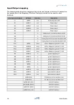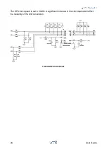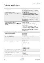
Never apply voltage levels outside the specified operating limits to AI1, AI2, AI3 or AI4.
Ox: Relays
Iono Pi has four single pole single throw power relays, with normally open contacts.
The relays are driven by distinct GPIO lines on the Raspberry Pi.
L1: On-board application LED
L1 is a green on-board LED that is controlled by a GPIO lines on the Raspberry Pi.
Note that, depending on the Raspberry Pi operating system’s configuration, the GPIO line
may be in a high state by default on startup, causing the LED to turn on before your
application takes control of the GPIO line.
TTL1: 1-Wire input/output
TTL1 is a bidirectional TTL I/O line (0÷5V), connected to the Raspberry Pi GPIO4 pin
through
a bidirectional level shifter. It can be used as a 1-Wire bus line, but can also serve
as a generic TTL I/O or as the DATA0 line of a Wiegand interface.
The TTL1 front-end circuit has a 4.7kOhm pull-up resistor.
Never apply voltages outside the 0-5V range to this pin to avoid damage to the Iono Pi
board and Raspberry Pi.
TTLx/DIx: TTL input/output or generic digital inputs
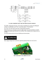
TTL2/DI1, TTL3/DI2 and TTL4/DI3 are dual-purpose pins. Using internal jumpers, they
serve as TTL I/O lines or generic digital inputs.
When TTL2/DI1 is configured as TTL I/O, it can be used as the DATA1 line of a Wiegand
interface, in combination with TTL1, or any other generic TTL I/O function.
TTL3/DI2, configured as TTL I/O, can be used as the DATA0 line of a second Wiegand
interface, or any other generic TTL I/O function.
WARNING
WARNING
16
User Guide


