


10
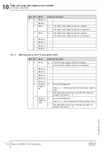
Data exchange with higher-level controller
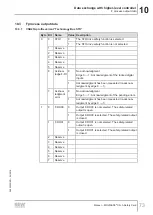
F process input data
Manual – MOVISAFE
®
CS..A Safety Card
84
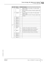
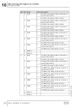
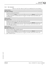
Byte Bit Name
Value Description
3
0
SLS1
0
The SLS1 drive safety function is not active, or
an error has occurred.
1
The SLS1 drive safety function is active.
1
SLS2
0
The SLS2 drive safety function is not active, or
an error has occurred.
1
The SLS2 drive safety function is active.
2
SLS3
0
The SLS3 drive safety function is not active, or
an error has occurred.
1
The SLS3 drive safety function is active.
3
SLS4
0
The SLS4 drive safety function is not active, or
an error has occurred.
1
The SLS4 drive safety function is active.
4
SSR1
0
The SSR1 drive safety function is not active, or
an error has occurred.
1
The SSR1 drive safety function is active.
5
SSR2
0
The SSR2 drive safety function is not active, or
an error has occurred.
1
The SSR2 drive safety function is active.
6
Reserve
7
Reserve
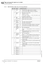
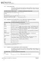
4
0
SLA1
0
The SLA1 drive safety function is not active, or
an error has occurred.
1
The SLA1 drive safety function is active.
1
SLA2
0
The SLA2 drive safety function is not active, or
an error has occurred.
1
The SLA2 drive safety function is active.
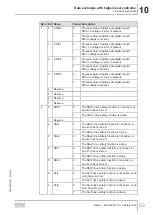
2
SSM1
0
The SSM1 drive safety function is not active, or
an error has occurred.
1
The SSM1 drive safety function is active.
3
SSM2
0
The SSM2 drive safety function is not active, or
an error has occurred.
1
The SSM2 drive safety function is active.
4
SSM3
0
The SSM3 drive safety function is not active, or
an error has occurred.
1
The SSM3 drive safety function is active.
5
SSM4
0
The SSM4 drive safety function is not active, or
an error has occurred.
1
The SSM4 drive safety function is active.
6
Reserve
7
Reserve
24842532/EN – 04/2018


