*26920468_0620*
Drive Technology \ Drive Automation \ System Integration \ Services
Revision
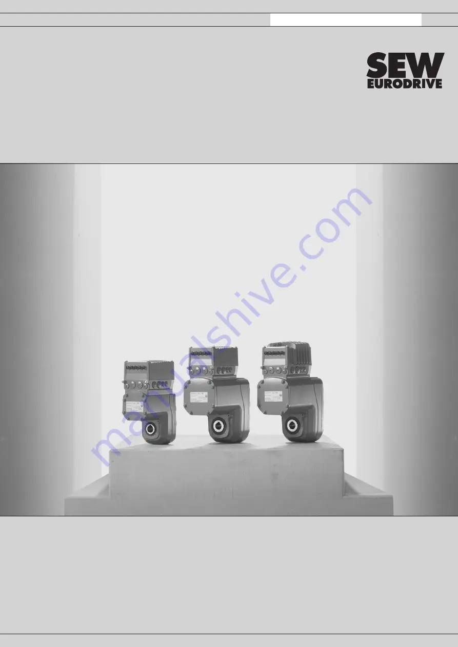
Mechatronic Drive Unit
MOVIGEAR
®
performance
(MGF..-...-C)
Edition 06/2020
26920468/EN
Страница 1: ...26920468_0620 Drive Technology Drive Automation System Integration Services Revision Mechatronic Drive Unit MOVIGEAR performance MGF C Edition 06 2020 26920468 EN...
Страница 2: ...SEW EURODRIVE Driving the world...
Страница 3: ...d by yourself Assignment of the optional plug connectors at MGF DBC and MGF DAC X1206 AC 400 V connection IN Assignment of the optional plug connectors at MGF DBC and MGF DAC X2242 AC 400 V connection...
Страница 4: ...cument Operating instructions MOVIGEAR performance MGF DBC C binary Operating instructions MOVIGEAR performance MGF DAC C AS Interface Operating instructions MOVIGEAR performance MGF DSI C EtherCAT SB...
Страница 5: ...GF DSI C 2 1 Product names and trademarks The brands and product names in this documentation are trademarks or registered trademarks of their respective titleholders 2 1 1 Trademark of Beckhoff Automa...
Страница 6: ...performance 6 3 Safety notes MOVIGEAR 3 1 Designated use 3 1 1 Restrictions under the European WEEE Directive 2012 19 EU You may use options and accessories from SEW EURODRIVE exclusively in connec t...
Страница 7: ...end not prefabricated CE UL AC 500 V 100 m 200 m HELUKABEL Li9YY 2 5 mm2 28118723 Open cable end not prefabricated CE UL AC 500 V 100 m 200 m HELUKABEL Li9Y11Y HF 2 5 mm2 28118707 Connection cable 4 0...
Страница 8: ...ection Identific ation Signal Brown 2 5 mm2 4 0 mm2 L1 L1 Line connection phase L1 Black 2 5 mm2 4 0 mm2 L2 L2 Line connection phase L2 Grey 2 5 mm2 4 0 mm2 L3 L3 Line connection phase L3 Green yel lo...
Страница 9: ...ector positions at the MGF DBC C drive unit The following figure shows possible plug connector positions X2242 X4141 X 2 3 1 X1203_1 X5136 X1206 X2242 X1203_1 X1203_1 X5505 X5504 X5136 X1203_2 X5504 X...
Страница 10: ...2242 AC 400 V connection OUT X 2 or 3 X1203_2 X5136 X5504 Yellow STO 3 core connection 3 X 2 or 3 X5505 Yellow STO 3 core connection 3 X 2 or 3 X4141 X5136 Digital inputs outputs X 2 or 3 X1203_2 X224...
Страница 11: ...DAC C drive unit The following figure shows possible plug connector positions X1524 X4141 X 2 3 1 X1203_1 X5136 X1206 X2242 X1203_1 X1206 X2242 X5505 X5504 X5136 X1203_2 X5504 X5505 X4141 X1524 X5135...
Страница 12: ...ow STO 3 core connection 3 X 2 or 3 X5135 X5505 Yellow STO 3 core connection 3 X 2 or 3 X1524 X4141 X5136 Digital inputs outputs X 2 or 3 X1203_2 X2242 X5135 Black Digital inputs X 2 or 3 X5504 X1524...
Страница 13: ...X1206 X4141 X 2 3 1 X1203_1 X1216 X1203_1 X1203_1 X1216 X5505 X5504 X1523 X2313 X1523 X2313 X1203_2 X2327 X5504 X5505 X4141 X4141 X2313 X1523 X5505 X5504 X2313 X1523 X1203_2 X1203_2 X2327 1 X1216 X232...
Страница 14: ...4 Yellow STO 3 core connection 4 X 2 or 3 X2313 X5505 Yellow STO 3 core connection 4 X 2 or 3 X1523 X4141 X1523 Light gray DC 24 V backup voltage input5 X 2 or 3 X5505 X4141 X2313 Light gray DC 24 V b...
Страница 15: ...ectivity Intercontec products if the order designation is not available in the online order system of Intercontec Order information The table below shows the order designations for connectors by TE Co...
Страница 16: ...following table shows information about this connection Function AC 400 V connection IN Connection type MQ15 X Power male plug connector without union nut MURR Elektronik current load max 16 A Connec...
Страница 17: ...bout this connection Function AC 400 V connection OUT Connection type MQ15 X Power female plug connector with union nut MURR Elektronik current load max 16 A Connection diagram PE A 3 2 1 B Assignment...
Страница 18: ...PA connection for AC 400 V and 24 V backup voltage IN Connection type M23 male male thread SEW insert 723 series SpeedTec equipment company TE Connectivity Intercontec products male coding ring black...
Страница 19: ...Cable cross sec tion operat ing voltage CE UL 28129326 HELUKABEL Li9YY Variable 2 5 mm2 AC 500 V M23 male coding ring black green M23 female coding ring black green CE UL 28127587 HELUKABEL Li9YY Var...
Страница 20: ...E UL 28129334 HELUKABEL Li9YY Variable 4 0 mm2 AC 500 V M23 male coding ring black green M23 female coding ring black green CE UL 28127579 HELUKABEL Li9YY Variable 4 0 mm2 AC 500 V Open M23 female cod...
Страница 21: ...m2 L1 Not pre fabricated Line connection phase L1 L1 U Black 2 5 mm2 4 0 mm2 L2 Not pre fabricated Line connection phase L2 L2 V Grey 2 5 mm2 4 0 mm2 L3 Not pre fabricated Line connection phase L3 L3...
Страница 22: ...ge OUT Connection type M23 female female thread with union nut SEW insert 723 series SpeedTec equip ment company TE Connectivity Intercontec products male coding ring black green protected against con...
Страница 23: ...on type Cable cross sec tion operat ing voltage CE UL 28129326 HELUKABEL Li9YY Variable 2 5 mm2 AC 500 V M23 male coding ring black green M23 female coding ring black green CE UL 28114426 HELUKABEL Li...
Страница 24: ...tage CE UL 28129334 HELUKABEL Li9YY Variable 4 0 mm2 AC 500 V M23 male coding ring black green M23 female coding ring black green CE UL 28114434 HELUKABEL Li9YY Variable 4 0 mm2 AC 500 V M23 male codi...
Страница 25: ...m2 L1 Not pre fabricated Line connection phase L1 L1 U Black 2 5 mm2 4 0 mm2 L2 Not pre fabricated Line connection phase L2 L2 V Grey 2 5 mm2 4 0 mm2 L3 Not pre fabricated Line connection phase L3 L3...
Страница 26: ...about this connection Function AC 400 V connection IN Connection type MQ15 X Power male plug connector without union nut MURR Elektronik current load max 16 A Connection diagram PE B 1 2 3 A Assignmen...
Страница 27: ...bout this connection Function AC 400 V connection OUT Connection type MQ15 X Power female plug connector with union nut MURR Elektronik current load max 16 A Connection diagram PE A 3 2 1 B Assignment...
Страница 28: ...unction DC 24 V backup voltage input Connection type M12 5 pin male L coded color light gray Connection diagram 1 4 2 3 Assignment Contact Signal Description 1 24V L1 DC 24 V input L1 for backup mode...
Страница 29: ...nction DC 24 V output backup voltage Connection type M12 5 pin female L coded color light gray Connection diagram 4 1 3 2 Assignment Contact Signal Description 1 24V L1 DC 24 V output L1 for backup mo...
Страница 30: ...splays 5 1 1 LED indicators EtherCAT SBusPlus The following figure shows the LEDs of the EtherCAT SBusPlus design DSI10A 0020 503 A S00 000 EtherCAT SBusPLUS MAC ID F ERR F RUN ERR RUN L A L A DRIVE 6...
Страница 31: ...perating state Parameterization No parameterization exists Error in parameterization Inconsistent parameterization Current parameter set is not consistent with the safety key Yellow Flashing quickly E...
Страница 32: ...tance of the module has not yet taken place Green Flashing quickly Device booting up or initializing Device in parameterization state Yellow Flashing slowly Device in the operating state with one or m...
Страница 33: ...tive Yellow Steady light Ready but unit inhibited Line voltage is OK The output stage is locked Green Flashes slowly 0 5 Hz Unit enabled but condition manual mode local mode The output stage is enable...
Страница 34: ...ake fault 13 5 24 Encoder 1 fault 16 5 8 10 20 27 Startup fault 19 1 9 Process data fault 20 2 11 Device monitoring fault 23 4 Power section fault 25 2 7 20 21 30 31 61 70 Parameter memory monitoring...
Страница 35: ...8 Control mode fault 10 2 99 Data Flexibility fault 11 7 8 Temperature monitoring fault 13 1 3 6 7 8 9 11 13 15 22 23 Encoder 1 fault 16 2 11 12 30 Startup fault 17 7 Internal processor fault 18 1 3 4...
Страница 36: ...ection with the EtherCAT SBusPLUS interface IN with bus activity OFF No Ethernet connection with the EtherCAT SBusPLUS interface IN LEDs L A OUT LED Meaning Green Illuminated Ethernet connection with...
Страница 37: ...and process data communication is possible ERR LED LED Meaning Off No fault The interface is in operating state Red Flickering Boot error A BOOT error has occurred INIT state has not been reached Howe...
Страница 38: ...nector configuration For more information refer to chapter Plug connector positions 6 3 2 6 7 6 2 2 3 4 5 1 18 16 22 50 1 56 2 501 562 22 30 32 56 2 1 69 2 501 562 18 18 18014423809130763 1 Straight p...
Страница 39: ......
Страница 40: ......
Страница 41: ......
Страница 42: ......
Страница 43: ......
Страница 44: ...SEW EURODRIVE Driving the world SEW EURODRIVE GmbH Co KG Ernst Blickle Str 42 76646 BRUCHSAL GERMANY Tel 49 7251 75 0 Fax 49 7251 75 1970 sew sew eurodrive com www sew eurodrive com...