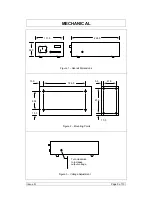
Setec BCE4 Скачать руководство пользователя страница 13

Cooling 

The BCE5 power supply has been design for convection cooling. It is, 
therefore, very important that its natural airflow is unimpeded. 
For maximum output power at maximum ambient temperature it is 
recommended that the following spaces above and below the power 
supply are provided. 
 

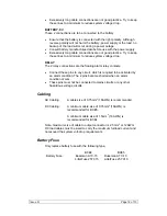
Horizontal (bench) mounting 

Vertical mounting 


60mm min 

60mm min 

20mm min 


Note: 

The maximum ambient operating temperature of the power 

supply is defined as the temperature of the air entering the bottom of the 
power supply. This may not be the same as the room temperature if the 
power supply is mounted above a heat source, or in a confined space. 
 
If the objects above and below the power supply do not restrict the 
airflow, (i.e. perforated metal) then the distances shown above may be 
reduced. For more information contact the manufacturer. 
 

Issue D 


Page 13 of 13


Содержание BCE4

Страница 1: ...SETEC MODEL BCE4 BCE5 USER S MANUAL Document No 010812 Issue D Page 1 of 13...

Страница 2: ...ALIA Phone 61 3 9763 0962 Fax 61 3 9763 8789 Email sales setec com au WARNING This product Contains Hazardous voltages which can cause death It should only be serviced by properly qualified personnel...

Страница 3: ...Protection 5 Battery LVD Operation 6 Indicators 6 Alarm 6 Output Voltage Adjustment 6 SPECIFICATION 8 MECHANICAL 9 MOUNTING 10 INSTALLATION 11 Personnel 11 Mounting Options 11 Connectors 11 Hooking Up...

Страница 4: ...the output Many other applications will be able to take advantage of these features Features include Light compact design High Efficiency Battery over discharge protection with automatic reset High re...

Страница 5: ...onditions an internal switch connects the battery in parallel with the load The average load must be less than the capability of the power supply to ensure there is a remainder available to float char...

Страница 6: ...ion incorporated against a reversed battery connection A reversed battery is left disconnected so that the LOAD output can still run the load from mains power The quiescent current drain on the batter...

Страница 7: ...the output connector with the battery disconnected Failure to disconnect the battery can result in incorrect output voltage setting and over charging of the battery may result The output voltage is fa...

Страница 8: ...Battery Reconnect 11 9 0 3V 20 5 0 6V Battery Hysteresis 1 7V typ 3 0V typ Battery Fuse 15A 32Vdc 10A 32Vdc Load Regulation 1 2 from set point taking into account all of line and load regulation and t...

Страница 9: ...ICAL 111 0 224 0 59 0 Figure 1 Overall Dimensions 63 0 186 5 15 3 81 6 47 8 13 0 5 5 10 0 Figure 2 Mounting Points Turn clockwise to increase output voltage Figure 3 Voltage Adjustment Issue D Page 9...

Страница 10: ...assis is 4mm M3 Screw Front Panel Figure 3 Front Panel Mounting Rubber Feet Flat Washer M3 x 8mm Screw Figure 5 Bench Mounting M3 Screw Maximum protrusion of M3 screw into chassis is 4mm Mounting Pane...

Страница 11: ...so it is important that the screw lengths are adhered to Connectors Input Mains IEC320 DC Output 6 Way female plugable type Pinout for the DC output connector is as follows Pin Function 1 0V 2 0V 3 Lo...

Страница 12: ...ng alarm relay contacts Connect these pins to any circuit which is required to be activated by an alarm condition The 2 pins become shorted when an alarm condition occurs These pins must not be connec...

Страница 13: ...mounting 60mm min 60mm min 20mm min Note The maximum ambient operating temperature of the power supply is defined as the temperature of the air entering the bottom of the power supply This may not be...

Отзывы: