


SerVision
UVG400 Installation Guide
Installing the UVG400 System
9
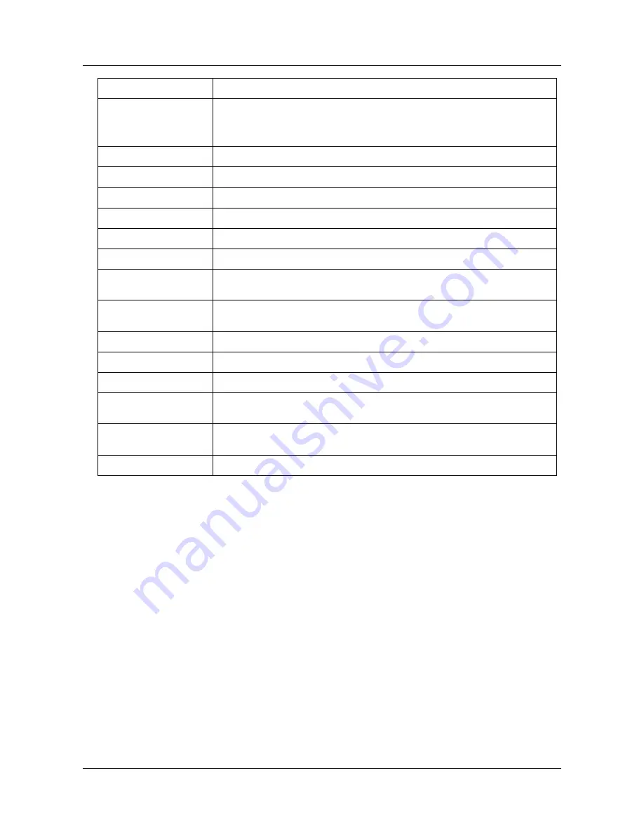
Connector/Control Description
Reset
Reset button. Use a pin to press the button when it is necessary to reset the unit
manually.
Note: Your configuration settings will not be lost during a reset.
Power
Connector for the power supply and, if required (see page 23)
Audio Out (Aout)
Connector for an external speaker or headphones (see page 18)
Audio In2 (Ain2)
Connector for an active microphone (see page 18)
Audio In1 (Ain1)
Connector for a passive microphone (see page 18)
TV Out
Connector for a CCTV monitor (see page 19)
Video In (Vin1–Vin4)
Connectors for video cameras (see page 10)
Ethernet Cable
Cable connecting the Video Gateway component of the UVG400 to the unit’s router.
Do not disconnect.
RS232/485
Serial (COM) port for PTZ controllers (see page 10), ADAM modules (see page 12),
or technicians' use
Mouse Connector
Mouse connector (for the supplied PS2 mouse only; see page 19)
USB Ports
Connectors for WiFi cards or cellular modems with USB adaptors (see page 21)
Sensors (In1 – In4)
Sensor connectors (see page 11)
Ethernet Out
10/100 Base-T LAN connector for connecting the unit to an external network (LAN
or WAN; see page 21.)
Ethernet In
Three 10/100 Base-T LAN connectors for connecting other devices to the internal
network managed by the UVG400’s router (see page 21)
Activators (Out1, Out2)
Activator connectors (see page 16)
Содержание UVG400
Страница 1: ...UVG400 Installation Guide September 2013...


