


SerVision
UVG400 Installation Guide
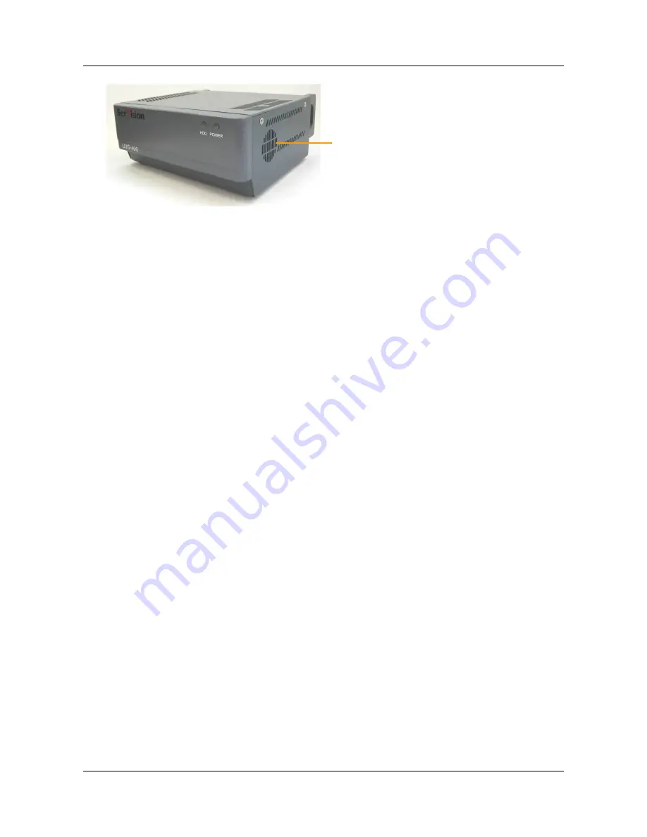
Internal speaker
Figure 14: Internal speaker
D
To connect a speaker or headphones:
1. Install the speaker in its desired location, if necessary.
2. Plug the speaker or headphone connector into the
Audio Out (Aout)
connector.
Connecting a CCTV Monitor
You can connect a CCTV monitor to the unit. The monitor offers an alternative way to view live or recorded video
from the UVG400. It is primarily useful if you want to view video when you are near the unit. For example, if the
UVG400 is set up in a grocery store, and you sit at the check-out counter, you can use a CCTV monitor to keep tabs
on parts of the store that you cannot see from your seat.
The following types of monitors can be used:
•
Surveillance monitors: Monitors that are designed to be plugged directly into surveillance cameras.
•
Entertainment monitors: Monitors that are intended to be plugged into portable DVD players in vehicles.
•
Standard television sets with AV connectors
When choosing a monitor to connect to the unit, ensure the monitor supports the video format used by the cameras
(NTSC or PAL). Some SECAM monitors will also work when the PAL video format is used.
To connect the monitor to the UVG400, you will need a cable with the following connectors:
•
An appropriate connector (BNC or RCA) for the Video In connector of the monitor. (Consult the monitor
documentation or your vendor to find out which kind of connector is required for the particular monitor you
are using.)
•
A BNC male connector to connect to the
TV Out
connector of the UVG400. (A cable with an RCA connector
can be used by attaching a BNC-to-RCA adaptor to the connector. See figure 9, page 10.)
D
To connect a CCTV monitor:
1. Install the monitor in its desired location.
2. Connect the Video In connector of the monitor to the
TV Out
connector of the UVG400, using a cable with an
appropriate connector (BNC or RCA) for the Video In connector of the monitor on one end, and a BNC male
connector on the other end.
Note:
If you are using a standard television set as a monitor, use the television’s AV connector as the Video
Input connector.
Connecting Devices to the UVG400
19
Содержание UVG400
Страница 1: ...UVG400 Installation Guide September 2013...


