


Section 3
Operation
Part Number 020003997
4/12
3-5
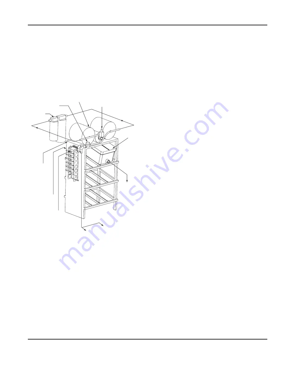
SYRUP DELIVERY SYSTEM
Your syrup location can vary depending on the volume of
beverages served and ease of accessibility. Your beverage
system may set in a back storage room or under the counter of
the dispenser. Configurations are almost limitless. Check the
temperatures expected for the storage location. Adverse
temperatures can affect the storage and quality of beverage
products. It is recommended the temperature of storage location
must not fall below 40°F (4°C) or rise above 90°F (32°C).
BACK ROOM PACKAGE
1.
Incoming tap water –
must be at a minimum dynamic
pressure of 40 psi and maximum static pressure of 55 psi.
2.
Carbonator Water pump motor –
Powers the water
pump. The water pump motor is part of the carbonator
pump deck.
3.
Carbonator Water pump –
Pumps tap water into the
carbonator tank. The water pump is part of the
carbonator. The incoming water for the carbonator must
be first run through the pump before connecting to the
proper cold plate inlet.
4.
Internal/External Carbonator tank –
Combines CO
2
gas and tap water to form carbonated water. The
“carbonator” is the carbonator tank, water pump and
water pump motor.
5.
CO
2
cylinder –
Holds highly pressurized carbon dioxide
(CO
2
). The CO
2
cylinder is a steel or aluminum cylinder
tank. CO
2
gas flows through the primary pressure
regulator.
6.
BIB pressure gauge –
Set for a minimum of 60 psi.
Indicates CO
2
pressure going to B-I-B pumps.
7.
Primary pressure regulator –
Lowers the CO
2
gas
pressure, to 100 psi, so the CO
2
gas will be at the
proper pressure to enter the carbonator regulator.
8.
Lowered outgoing pressure –
Set for 75 psi. Gauge
indicates lowered outgoing pressure from the CO
2
cylinder after being routed through the primary pressure
regulator at 100 psi.
9.
Secondary pressure regulator –
Lowers the CO
2
gas
pressure before the CO
2
gas flows to the syrup pump.
CO
2
pressure activates the syrup pump.
10.
Syrup pump –
Draws syrup out of the bag-in-box syrup
package. Syrup flows through the syrup lines to the
dispenser for chilling, then dispensing. There is a syrup
pump for each bag-in-box syrup system.
11.
Bag-In-Box syrup cartons –
Box which contains a
plastic bag, filled with syrup.
RACKING
Regardless if you are working on a B-I-B or Figal system, a
place will be designated for placement of the product. A rack
(or shelf) system affords systematic placement and
complete usage of the beverage paid for. The B-I-B rack
allows the boxes to lay properly for syrup dispersal. Please
check with your B-I-B syrup supplier. Some boxes must be
slightly tilted down, while others may be in virtually any
position. The Figal tank rack keeps the newer and full tanks
organized at one end of the beverage line with the partial
tanks at the other.
B-I-B
The Bag-In-Box system refers to a plastic disposable bag.
The B-I-B normally contains 5 gallons of syrup, however
some locations offer 2-1/2 gallon B-I-B units. This plastic bag
is then held inside a cardboard or other container. B-I-B
systems are for post-mix applications only.
PUMPS
The syrup in a B-I-B system is delivered to the beverage
system through gas operated pumps. These pumps extract
the syrup out of the bags, forcing the syrup throughout the
system.
AUTO BAG SELECTORS
These are used on higher volume B-I-B systems where two
or more bags of the same product are connected to one
pump and one system. An auto bag selector is essentially a
valve that automatically changes from one bag (or series of
bags) to another bag (or series of bags) of syrup as the bags
empty, allowing a constant flow of product.
From Water Supply
To Noncarbonated
Water Inlet Barb
Water to
Carbonator
Pump
Filter
Water Regulator
40–55 PSI
Booster System
(If Required)
To CO
2
Manifold (BIB
Pumps) from
CO
2
Supply
60 PSI
To Syrup Inlet
Barbs on Unit
To BIB Pumps
from BIB
To BIB
Pump
BIB
Содержание SV-200 SCI
Страница 6: ...Table of Contents continued iv Part Number 020003997 4 12 ...
Страница 33: ...Section 3 Operation Part Number 020003997 4 12 3 9 Control Logic Matrix Flavor Magic ...
Страница 34: ...Operation Section 3 3 10 Part Number 020003997 4 12 THIS PAGE INTENTIONALLY LEFT BLANK ...
Страница 44: ...Maintenance Section 4 4 10 Part Number 020003997 4 12 THIS PAGE INTENTIONALLY LEFT BLANK ...
Страница 49: ...Section 5 Before Calling for Service Part Number 020003997 4 12 5 5 THIS PAGE INTENTIONALLY LEFT BLANK ...
Страница 50: ...Before Calling for Service Section 5 5 6 Part Number 020003997 4 12 THIS PAGE INTENTIONALLY LEFT BLANK ...
Страница 51: ......