22
22
Robotics Interface Board
22
30
GND
Gnd
0
Ground connection
31
ET_TD+
Ethernet
Ethernet transmit data + output
See note 2 below
32
GND
Gnd
0
Ground connection
33
ET_TD-
Ethernet
Ethernet transmit data - output
See note 2 below
34
GND
Gnd
0
Ground connection
35
Reserved
36
GND
Gnd
0
Ground connection
37
GND
Gnd
0
Ground connection
38
Reserved
39
Reserved
40
Reserved
41
GND
Gnd
0
Ground connection
42
GND
Gnd
0
Ground connection
43
PWR_IN
P
4.5
–
30V
Power input
See section 3.7
44
PWR_IN
P
4.5
–
30V
Power input
See section 3.7
Note 1
: The level of the GP1 pin of the AsteRx-m3 OEM (pin#9 of the 60-pin connector,
see 2.5.2) must be low for the EVENT pins to be functional.
Note 2
: On-board magnetics. The Ethernet pins can directly be routed to an Ethernet
connector.
3.4
LEDs
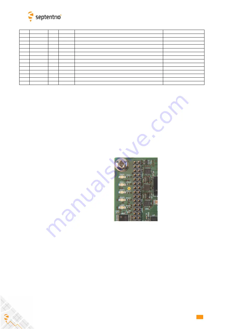
The GP2 LED reflects the status of the GP2 pin (pin#44 of the 60-pin connector of the
AsteRx-m3 OEM, see section 2.5.2). The LED lights when GP2 is high. The behavior of the
GPLED and of the LOGLED is described in Appendix A.
LAN activity LED
Not Used (always OFF)
GP2
GPLED
LOGLED
Содержание AsteRx-m3
Страница 1: ...AsteRx m3 Product Group Hardware Manual Version 2 2 0 ...
Страница 18: ...18 18 AsteRx m3 OEM 18 ...


