


Specifications
7
Doc 01-G0181
Rev A
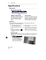
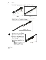
Figure 1
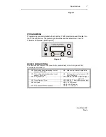
PROGRAMMING
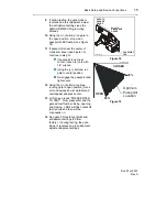
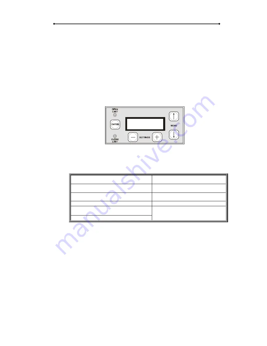
Programming is accomplished with a 5 button, 2 LED membrane switch located on
top of the control box. Programming instructions are presented on a 2 row, 16
character LCD screen (see Figure 2).
Sentex
systems
01-16169F1
Figure 2
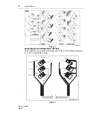
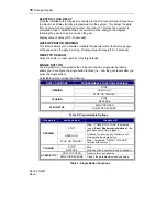
DEVICE CONNECTIONS
Connections are made to the lower half (exposed half) of the front panel PCB.
Provisions are made for:
J2
– Safety edge open (trailing edge contact
sensor); N/O & N/C
J8
– Hold open (no timer); Single Button
J3
– Safety edge close (leading edge contact
sensor); N/O & N/C
J9
– Photo eye (non-contact sensor); N/O
& N/C Contacts
J4
– 3 loop detectors
JP5, JP6, JP7, & JP8
– Output relays for
lights, etc.
J5
– Close; Open w/ Timer
JP5, JP6, JP7
– Master/Slave connections
J6
– Not Used
J7
– Stop (required N/C connection)
JP9
– 24 VDC power
JP12
– 24 VAC power
JP14
– 115 VAC power