Basic Setup and Device Connections
14
Doc 01-G0181
Rev A
Basic Setup and Device
Connections
Setup
WARNING
Use only qualified electricians. Serious injury or death can occur from
electrical shock or entanglement in operator.
NOTE:
Follow manufacturer’s instructions for safety devices such as edges
and photo eyes.
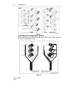
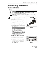
UNLOCKED
LOCKED
01-G0181F16
Figure 16
1
Install the stop button (normally closed)
on J7 terminals. The operator will not
run without this button.
2
Turn
off
line power and battery power.
3
Release (unlock) the quick disconnect
(see Figure 16) and check that the gate
swings freely.
4
Lock quick disconnect (see Figure 16).
5
Turn line power on. The LCD screen
should display the "Limits Menu" if limits
have not been set.
CAUTION
The unit should not move. If it does,
shut off power and check all
connections before proceeding.
NOTE:
The operator is shipped from the
factory without limits. If limits have been
previously stored, the men will read
“OPERATION NORMAL”.
6
Check to see that the Limits’ LEDs are
off.
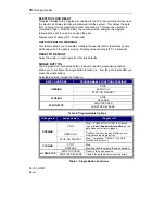
7
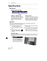
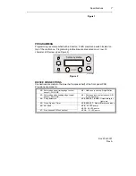
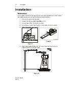
See Figure 17. Screen should read
“LIMITS MENU”; press enter and + to
set limits.
8
Using the {+/-} buttons, run gate to the
closed position (crank and extension
arms to be lined up) and press enter to
set the close limit.
Sentex
systems
01-16169F1
Figure 17


