background image

It is now time to integrate the Alarm Keypad with the controller, which is achieved by instructing certain 
readers to link to the panel.  In our simple example, we are going to link it to Reader 1, which will mean 
that, when armed, the door will be locked and ordinary users will not be able to enter.  If a Supervisor uses 
the door, a timer will commence during which they will be able to disarm the alarm with their PIN code. 
 
Open the reader window by going to 

Parameter

Controller

, and clicking on the tab 

Readers

.  You now need 

to select the reader in question, and expand it by clicking on its grey ellipse (three dots) button. 
 

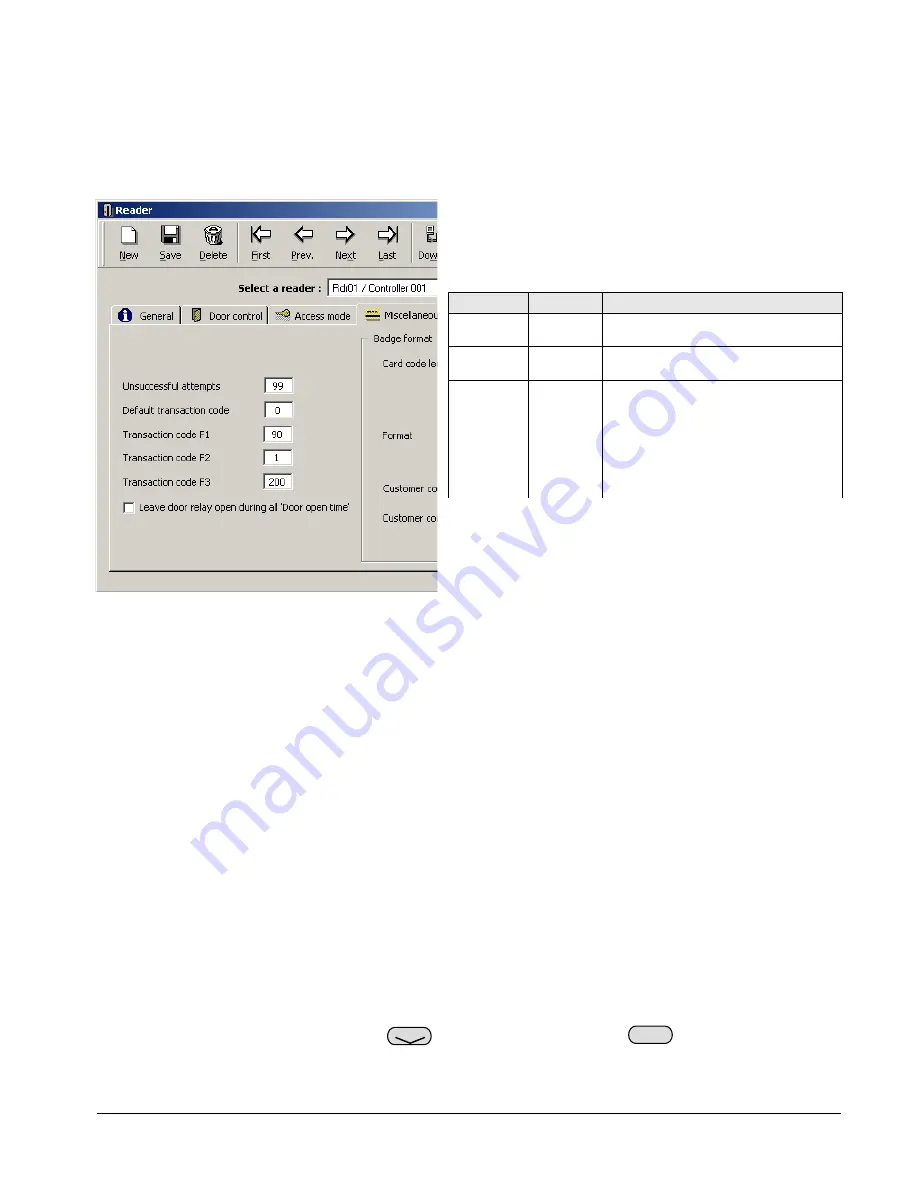
Once the reader window has been expanded it is time to 
link it to the Alarm Keypad panel.  In order to achieve 
this, three commands are used and entered into the 
Transaction Code boxes F1-F3, as follows: 
 

MNMSC0107_ALARMKEYPAD:  Alarm Keypad Installation and User Manual                                                                7/11 


Example:  Our Alarm Keypad panel is now setup and 
configured.  In this simple example, it currently has 1 
Alarm Zone, which consists of Input 1 and Reader 1.  We 
also have 1 supervisor who can arm/disarm the system. 

Code F# 

Example

Notes 


4. USING THE SYSTEM.  

 
In this section we will look at using the Alarm Keypad panel.  Whilst the panel has a number of control 
buttons, there are currently only three distinct functions which can be accessed by authorised users.  
Additional functions are due to be introduced in future versions of the software. 
 
Before using the system, it is worthwhile checking that it has set itself up correctly.  The LCD panel on the 
front of the Alarm Keypad should be showing the current date and time on the top line, and the words 

TYPE 

YOUR CODE

 on the bottom.  If it isn’t, try denying power to the unit for a few seconds, then returning it. 


4.1 Arming 

Perhaps the most important function of the Alarm Keypad is the ability to arm alarms.  A supervisor has the 
power to arm/disarm any of these Alarm Zones win their PIN, as defined in the 

Cardholders

 window. 

 
In order to arm an Alarm Zone, you need to enter the following: 
 

PIN code 


Alarm Zone 


The unit will shown 

ARMED

 and a long beep is heard.  The red 

ARM

 light on the Alarm Keypad will 

begin to flash for the pre-defined delay.  Once this delay has elapsed, the red 

ARM

 light will go solid, and 

F1 90 

90 is a static command that tells the 
software an Alarm Keypad is present. 

F2 1 

Confirms to which Alarm Zone this 
reader belongs, see section 5 for more. 

F3 200 

The entry/exit delay time given to a 
valid supervisor to disarm an active 
alarm or exit a door after arming. 
This number is always 192 + # where # 
is the desired time in seconds. 
Thus, the value 200 will give a delay of 
8 seconds (192 + 8 = 200).

Arm 

Bypass

Содержание ALARM KEYPAD

Страница 1: ...SENSOR ALARM KEYPAD INSTALLATION AND USER MANUAL MNMSC0107_ALARMKEYPAD January 2007 ...

Страница 2: ...NG FIRMWARE 3 3 SETTING UP THE SYSTEM 4 3 1 INSTALLING THE RCB 4 3 2 WIRING THE ALARM KEYPAD 4 3 3 SOFTWARE SETUP INITIAL 5 3 4 SOFTWARE SETUP GUARDPOINT PRO 6 4 USING THE SYSTEM 7 4 1 ARMING 7 4 2 DISARMING 8 4 3 STATUS 8 5 ALARM ZONES 9 5 1 LINKING ZONES 9 5 2 MULTIPLE ZONES 9 5 3 SHARED INPUTS 10 APPENDIX A TECHNICAL SUPPORT 11 ...

Страница 3: ...f codes that tell the controller how to behave in certain situations In most cases your new controller should already have the latest firmware loaded but there may be cases where you wish to set up an Alarm Keypad on an older panel In order to check the date of the firmware on your controller you will need to start GuardPoint Pro and to make sure you have comms Once the application is communicatin...

Страница 4: ...idea to handle the chips as little as possible and if you are installing in an area with high static such as nylon carpets you should touch something metal before handling the chips in order to dissipate any charge that has built up 3 2 Wiring the Alarm Keypad Once the RCB chips and terminal block are installed you need to ensure that everything is correctly wired The wiring configuration for the ...

Страница 5: ...lick it or right click it and select Open from the menu The file should now load via the Windows Notepad application You will now need to check for two separate lines in the file These can be found either by press Ctrl F on the keyboard or going to the Edit menu and selecting the option Find You can then type the name into the search box to quickly check through the whole file for it 3 1 Controlle...

Страница 6: ...e we are going to use the default WP Always so that the input group will be available whenever required From the menu option Event Handling select Event Handling Program then click New Give the event a name then click on the Alarms tab then on the View Group of Inputs radio button as shown on the left Ensure that a green tick is next to the input group we defined earlier and that the Weekly Progra...

Страница 7: ...a number of control buttons there are currently only three distinct functions which can be accessed by authorised users Additional functions are due to be introduced in future versions of the software Before using the system it is worthwhile checking that it has set itself up correctly The LCD panel on the front of the Alarm Keypad should be showing the current date and time on the top line and th...

Страница 8: ...e has locked down its door s Since the Alarm Keypad panel is installed inside the building a supervisor must first pass their card at the reader in order to gain access When this pass is detected the Alarm Keypad panel will go into Alarm Delay mode and the red ARM light will begin to flash for the pre defined delay The supervisor now has that time to go to the panel and carry out the disarming pro...

Страница 9: ...ple Zones he creation of any Alarm Zone is done first by defining which inputs are to be part of that zone In the t of selected ontrol of multiple zones can be achieved from a single Alarm Keypad panel where multiple alarms and or T box marked Transaction code F2 In the example on the right reader 1 is linked to Alarm Zone 1 Note that whilst an Alarm Zone can have m readers linked to it a reader c...

Страница 10: ...l way As a result input 4 of Controller 2 becomes armed d but the shared any situation where Alarm Zones have shared inputs the Alarm Keypad will automatically ignore any g Controller 1 Controller 2 IC1604 marked E Input 2 is wired to an alarm Zone 5 N 2 and C Zone 3 Alarm Panel Two is used to control the inputs of controllers D Zone 4 and E Zone 5 5 In same bus Let s go back to our example of Dom...

Страница 11: ... support department Support is available from 08 30 to 17 30 Monday to Friday and we are happy to answer your questions or to guide you through any aspect of your installation Sensor Access Technology Ltd Technical Support Team Sensor House Westergate Road Brighton BN2 4JZ support sensoraccess co uk 44 0 870 890 1154 Manuals Installation Guides Datasheets and Application Notes are available from o...

Отзывы: