


21
Performing a frequency scan for wireless microphone
systems
The NET 1 selects one rack-mount receiver from each of the frequency ranges
to perform the frequency scan. The frequencies of the selected channel bank
are assigned to the connected receivers of this frequency range.
Subsequently, the frequencies are transferred to the corresponding portable
transmitters.
Note:
When you have connected both monitoring and microphone systems to
the NET 1, you first have to perform the frequency preset scan for the
monitoring system. (see “Performing a frequency scan for wireless
monitoring systems (IEM)” on page 18).
Switching the transmitters on/off
왘
Switch on
all rack-mount transmitters (IEM)
connected to the NET 1.
왘
Switch off
all portable transmitters
that are to be configured via the NET 1.
Performing the frequency scan
왘
Press and hold the
MODE
button
on the NET 1.
The NET 1 selects one rack-mount device from each of the frequency
ranges. The “CHANNEL” LEDs
assigned to these devices light up.
When two NET 1 are daisy-chained, pressing the
MODE
button
automatically determines the “master” NET 1. The “REMOTE” LED of the
“slave” NET 1 lights up and its
MODE
button
is deactivated.
왘
On the NET 1, press the channel button
corresponding to the receiver.
The corresponding “CHANNEL” LED
and the yellow “SCAN” LED
쐋
flash
slowly.
Note:
The results of any prior frequency scan are overwritten.
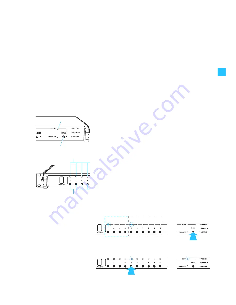
Example:
The connection groups 1 to 4 of the NET 1 are occupied by transmitters (IEM).
The connection groups 6 to 10 are occupied by rack-mount receivers. After
pressing the
MODE
button
, the green “CHANNEL“ LEDs
for the first rack-
mount transmitter (connection group 1) and the first rack-mount receiver
(connection group 5) light up. The “CHANNEL“ LEDs
of the other rack-
mount devices do not light up, i.e. they belong to the same frequency range.
After pressing the channel button
, both the “CHANNEL“ LED
of the rack-
mount receiver and the yellow “SCAN” LED
쐋
flash.
Wireless
monitoring system
Wireless microphone
system
1.
2.


