10 GND
11 A(+)
12 B (-)
10 GND
11 RX
12 TX
13 DI1
14 DI2
15 +12V
16 GND
17 DI3
18 DI4
0V
Max 24V
C
12V 20mA
13 DI1
14 DI2
15 +12V
16 GND
17 DI3
18 DI4
13 DI1
14 DI2
15 +12V
16 GND
17 DI3
18 DI4
0V
2
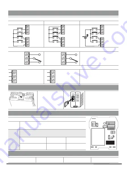
DIGITAL INPUTS
Internal power supply NPN
Internal power supply PNP
External power supply PNP
2
DIGITAL OUTPUTS
The module has two
digital
outputs with free contacts.
The figures show the internal relay
contacts available.
2
COM2 SERIAL PORT
RS485
SERIAL
PORT
(SW2=OFF )
RS232
SERIAL
PORT
(SW2=ON )
The module has a
serial port
COM2
available
terminals 10-11-12
at
.
This port can be configured
through the SW2 switch.
ELECTRICAL CONNECTIONS
DIP-SWITCHES
SW1
All the DIP-Switches to the
position.
OFF
0
For further informations please refer to the:
USER MANUAL
SW2
RS232 o RS485 configuration
r
2
on terminals 10-11-12 (serial port COM )
RS232
ON
1
RS485
OFF
0
SETTINGS
SIM-CARD AND SD-CARD INSERTING
ENGLISH -
8/8
t
Inserting the SIM card
into the rear slot at the
side of the IDC10
connector.
Inserting the MicroSD or
card
the microSHDC
, into the
ax
side slot. M
32 GB.
Push-push connector
for insertion and removal.
N.O.2=22
CO.2=23
N.C.2=24
N.O.1=19
CO.1=20
N.C.1=21
Technical support
Product Informations
CONTACTS
DEBUG PORT
SW1
DEFAULT setting
1 2 3 4 5 6 7 8
È È È È È È È È
PS1
2sec. SD unmount
6sec.
Power OFF
SW2
PS1
SW1
SW2
Ç
RS232
È
RS485
Warning:
disconnect power
supply before servicing device
Ç
1
ON
È
0
OFF
SIM


