


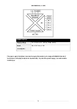


USER MANUAL
–
Z-D-IN
11
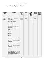
Overflow bits can be written to 0 for
reset.
Counter 1
16 bit counter (from 0 to 65535)
The value is stored into a non
volatile RAM (FeRAM).
The Counter value can be written
Unsigne
d 16 bits
R/W
(Non volatile)
-
40003
2
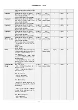
Counter 2
16 bit counter (from 0 to 65535)
The value is stored into a non
volatile RAM (FeRAM).
The Counter value can be written
Unsigne
d 16 bits
R/W
(Non volatile)
-
40004
3
Counter 3
16 bit counter (from 0 to 65535)
The value is stored into a non
volatile RAM (FeRAM).
The Counter value can be written
Unsigne
d 16 bits
R/W
(Non volatile)
-
40005
4
Counter 4
16 bit counter (from 0 to 65535)
The value is stored into a non
volatile RAM (FeRAM).
The Counter value can be written
Unsigne
d 16 bits
R/W
(Non volatile)
-
40006
5
Counter 5
(16 bit mode)
16 bit counter (from 0 to 65535)
The value is stored into a non
volatile RAM (FeRAM).
The Counter value can be written.
If configured to 32 bit use the
registers:
40019 (LSW)
40020 (MSW)
Unsigne
d 16 bits
R/W
(Non volatile)
-
40007
6
Filter
Filter (from 1 to 254) in ms applied
to all input-signals (except IN5 if
bit7 of the register 40009 is = 1).
Limit values:
if
=1[ms]=filtering
noise
with
frequency > 1kHz (max frequency
allowed 1KHz)
if =254[ms]=filtering noise with
frequency>4Hz (max frequency
allowed 4Hz)
R/W (*)
(Non volatile)
3 [ms]
40008
7
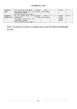
Configuration
Flags
Bit 0 Input Logic
If Bit0 = 0 Direct Input logic (0 =
open, 1 = close)
If Bit0 = 1 inverse Input logic (1 =
open, 0 = close)
Bit 1 Count mode
If Bit1 = 0 upcounter
If Bit1 = 1 downcounter
Bit 2 RS485 Delay
If Bit2=0 no pause between the
end of Rx message and the start of
Tx message
If Bit2=1 insert a pause between
the end of Rx message and the
start of Tx message
Bit 3 RS485 Parity Bit
If Bit3=0 no parity
If Bit3=1 bit parity ON
Unsigne
d 16 bits
R/W (*)
(Non volatile)
0
40009
8


