
2
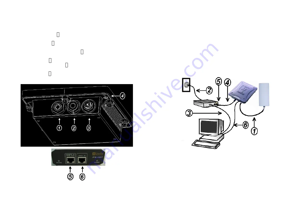
1.2 Locate the Router/Bridge and Inline Power
Injector Ports
Special
Ethernet port 1 for connecting the MIL-C-5015 style Ethernet
Cable
Special
serial port 2 for connecting the MIL-C-5015 style RS-232
console port cable
Reverse Polarity-N Male connector 3 for connecting the antenna or
RF cable.
Grounding port 4.
Power & Data output port 5 for connecting the other of the MIL-C-
5015 style Ethernet Cable
Data input port 6 for connecting the Ethernet Cable to a Hub Switch
Router or a PC.
3
1.3 Preparing
Installation
Before installing your Outdoor Wireless LAN system for your outdoor
application in a hard-to-reach location, we recommend that you configure
and test all the devices first.
For configuring the Outdoor Router/Bridge, you need follow the quick steps
below to power up your Router/Bridge:
Step 1:
With the unit powered off, attach one end of the RF cable to the
antenna connector and then connect the antenna to the other end of the RF
cable as shown in following:
Step 2
Plug the female end of the power cord into the Inline Power Injector,
and then plug the male end of the power cord into a power outlet or power
strip. The Power LED on the front of the Inline Power Injector will light up.
Step 3
Run the cross over Ethernet cable (included in your package) from
Data Input Port (on the front of the Inline Power Injector) to the Ethernet
Port on a PC.
NOTE:
This connection is required for setting up initial configuration
information. After configuration is completed, this cable will be removed,