
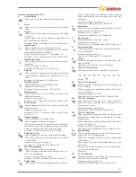


500
Allows the selection of the required graphic interface:
XE (Easy Mode)
XA (Advanced Mode)
XP (Professional Mode)
Allows access to the higher set-up levels:
USER:
user
SERV:
service
SELCO:
Selco
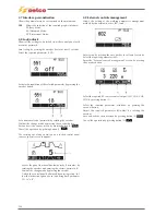
551 Lock/unlock
Allows the locking of the panel controls and the inser-
tion of a protection code (consult the “Lock/unlock”
section).
552 Buzzer
tone
Permits adjustment of the buzzer tone.
Minimum Off, Maximum 10, Default 5
553 Contrast
Permits adjustment of the display contrast.
Minimum 0, Maximum 50
601
(U/D) Adjustment step
Permits adjustment of the variation step on the up-
down keys.
Minimum Off, Maximum MAX, Default 1
602
CH1, CH2, CH3, CH4 External parameter
Allows the management of external parameter 1 (mini-
mum value, maximum value, default value, parameter
selected).
(Consult the “External controls management” section).
606 U/D torch
Allows the management of the external parameter
(U/D). 0=Off, 1=A
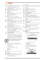
751 Current
reading
Allow the real value of the welding current to be dis-
played.
Allows the welding current display method to be set.
752 Voltage
reading
Allows the real value of the welding voltage to be dis-
played.
Allows the welding voltage display method to be set.
801 Guard
limits
Allows the setting of the warning limits and of the guard
limits.
Allows the accurate control of the various welding
phases (consult the “Guard limits” section).
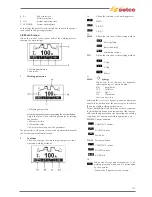
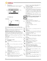
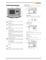
3.5 Programs screen
1 General
Allows the storage and management of 64 welding pro-
grams which can be personalised by the operator.
1 Process of the selected program
2 Welding methods
3 Current pulsation
4 Number of the selected program
5 Main parameters of the selected program
6 Description of the selected program
7 Measurements
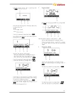
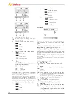
2 Program
storage
Enter the “program storage” menu by pressing button
for at least 1 second.
Select the required program (or the empty memory) by
rotating the encoder.
Program stored
Memory empty
Cancel the operation by pressing button (2)
.
129
Содержание Genesis 1700 AC/DC
Страница 1: ...Genesis 1700 AC DC Genesis 2200 AC DC MANUALE DI RIPARAZIONE REPAIR MANUAL ...
Страница 51: ...161 PFC S POWER COMPONENTS D11 IG1 IG2 D1 D7 CN3 M1 CN4 CN5 CN8 CN7 M2 CN6 ...
Страница 52: ...162 PFC STAGE LEDS INDICATIONS PFC s POWER COMPONENTS L2 L1 IG1 IG2 D1 CN6 D7 D11 ...
Страница 54: ...164 INVERTER STAGE CN3 M1 CN4 CN5 CN8 CN7 M2 Inverter IMS power module ...
Страница 62: ...172 15 Remove pcb T3 PFC s POWER COMPONENTS IG1 IG2 D1 NTC1 Unscrew torque screw at 2 2N mt ...
Страница 64: ...174 DIODES AND PFC IGBT ORIENTATION Landmark for assembling ...
Страница 67: ...177 12 4 Thermic caps inverter side NTC1 T3 CN11 ...
Страница 69: ...179 12 5 Thermic caps secondary side T1 T2 15 14 434 CN3 CN2 ...
Страница 74: ...184 15 14 439 15 14 42901 L3 L4 L1 L2 ...
Страница 75: ...185 Gas valve flow chart signal Pipe 38 39 ...
Страница 79: ...189 CN6 15 14 415 CN3 15 14 431 FLAT A FLAT B Inverter commands Boost commands ...
Страница 80: ...190 By pass relais flow chart Gas valve ELVI Fan M1 and M2 command signal ...
Страница 81: ...191 HF command signal AC command signal Torch switch buttons signals ...
Страница 88: ...198 HF pulse in TIG AC HF pulse in TIG DC ...
Страница 113: ...223 19 SCHEMI ELETTRICI E DI COLLEGAMENTO WIRING DIAGRAMS AND CONNECTION GENESIS 1700 AC DC FP279 ...
Страница 114: ...224 GENESIS 2200 AC DC FP279 ...
Страница 115: ...225 GENESIS 1700 AC DC FP216 ...
Страница 116: ...226 GENESIS 2200 AC DC FP216 ...
Страница 118: ...228 20 CONNETTORI CONNECTORS GENESIS 1700 AC DC FP279 GENESIS 2200 AC DC FP279 ...
Страница 119: ...229 GENESIS 1700 AC DC FP216 GENESIS 2200 AC DC FP216 ...
Страница 120: ...230 21 LISTA RICAMBI SPARE PARTS LIST 55 08 013 55 08 014 GENESIS 1700 AC DC FP279 GENESIS 2200 AC DC FP279 ...
Страница 122: ...232 55 08 022 55 08 023 GENESIS 1700 AC DC FP216 GENESIS 2200 AC DC FP216 ...


