


212
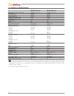
13) CALIBRATIONS
Calibrations procedure
Following description is for calibration procedure, for
offset signal and gain signal.
The offset calibration (set.up 704)
should be performed in case of complete or partial sw reflashing , or in case the measurement
in no load circuit are different from “0”. The calibration is not required in case of pcb replacement (boards are just Factory cali-
brated) or first customers setting.
The gain calibration (set.up 701)
should be performed only if the real output parameters exceed the maximum tolerance admitted
(± 2,5% maximum rated welding current).
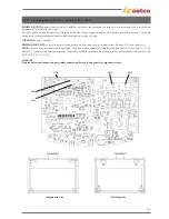
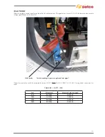
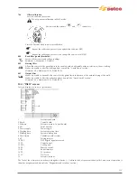
13.1) Offset calibration (only for unit with FP 15.22.279)
• Set the power source in TIG DC mode, not particular adjustment are required as well setting.
• Short circuit the output
&
socket, a big cable section is not necessary, just simple short circuit with cupper clamp
(the calibration will be done at zero current, see fig. 13 A).
• Press and hold the encoder /button till enter on set up menu (0 mark on display).
• Turn clockwise till
500
is marked, then valid with encoder and rotate to Serv menu then again valid, turn clockwise the encoder
to reach code
358
(password).
• On
358
valid again pressing encoder and turn clockwise to parameter
704
(offset adj. will appear on screen see fig. 13 B) then
valid using button
v
and will appear hourglass picture for a while; after automatically return to show on screen
704.
• Turn anticlockwise to set-up
0
and exit, otherwise for faster exit on set-up 704 press directly button save&exit.
The calibration is done!
Fig. 13 A
Fig. 13 B
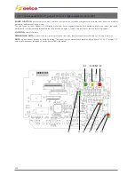
13.2) Current calibration (to be done after 704 calibration)
• Set the power source in TIG DC mode, not particular adjustment are required as well setting. Suggested current value to do the cali-
bration is at 200 (150) amp.
As alternative could be used the MMA process connected to relative static load, in case consult sec. instruments and conventions for
right powering. The calibration preview current circulation in this sense connect all necessary tools for measurement and welding (see
fig. 13C).
• Press and hold the encoder/button till enter on set up menu (0 mark on display).
• Turn clockwise till
500
is marked, then valid with encoder and rotate to
Serv
menu then valid again, turn clockwise the encoder to
reach code
358
(password).
• On
358
valid pressing encoder and turn clockwise to parameter
701
(current adj. will appear on screen see fig. 13 D).
• On 701 valid and activate the switch torch button for TIG welding or connect the static load for MMA welding. The welding unit will
start delivery output current (approximately 200 (150) amp. and the screen will show
784
(factory calibration).
• The calibration demand to equalize the value read from calibrated amp meter instrument to the value 200 amp. (the value that we
just set in the first step). This operation is possible turning the encoder till reached the right amperage. Once the amperage delivered
match with the pre setted value, confirm pressing the encoder.
• Turn anticlockwise to set-up
0
and exit, otherwise for faster exit on set-up 701 press directly button save&exit.
The calibration is done!
Fig. 13 C Fig. 13 D
Содержание Genesis 1700 AC/DC
Страница 1: ...Genesis 1700 AC DC Genesis 2200 AC DC MANUALE DI RIPARAZIONE REPAIR MANUAL ...
Страница 51: ...161 PFC S POWER COMPONENTS D11 IG1 IG2 D1 D7 CN3 M1 CN4 CN5 CN8 CN7 M2 CN6 ...
Страница 52: ...162 PFC STAGE LEDS INDICATIONS PFC s POWER COMPONENTS L2 L1 IG1 IG2 D1 CN6 D7 D11 ...
Страница 54: ...164 INVERTER STAGE CN3 M1 CN4 CN5 CN8 CN7 M2 Inverter IMS power module ...
Страница 62: ...172 15 Remove pcb T3 PFC s POWER COMPONENTS IG1 IG2 D1 NTC1 Unscrew torque screw at 2 2N mt ...
Страница 64: ...174 DIODES AND PFC IGBT ORIENTATION Landmark for assembling ...
Страница 67: ...177 12 4 Thermic caps inverter side NTC1 T3 CN11 ...
Страница 69: ...179 12 5 Thermic caps secondary side T1 T2 15 14 434 CN3 CN2 ...
Страница 74: ...184 15 14 439 15 14 42901 L3 L4 L1 L2 ...
Страница 75: ...185 Gas valve flow chart signal Pipe 38 39 ...
Страница 79: ...189 CN6 15 14 415 CN3 15 14 431 FLAT A FLAT B Inverter commands Boost commands ...
Страница 80: ...190 By pass relais flow chart Gas valve ELVI Fan M1 and M2 command signal ...
Страница 81: ...191 HF command signal AC command signal Torch switch buttons signals ...
Страница 88: ...198 HF pulse in TIG AC HF pulse in TIG DC ...
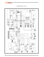
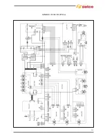
Страница 113: ...223 19 SCHEMI ELETTRICI E DI COLLEGAMENTO WIRING DIAGRAMS AND CONNECTION GENESIS 1700 AC DC FP279 ...
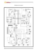
Страница 114: ...224 GENESIS 2200 AC DC FP279 ...
Страница 115: ...225 GENESIS 1700 AC DC FP216 ...
Страница 116: ...226 GENESIS 2200 AC DC FP216 ...
Страница 118: ...228 20 CONNETTORI CONNECTORS GENESIS 1700 AC DC FP279 GENESIS 2200 AC DC FP279 ...
Страница 119: ...229 GENESIS 1700 AC DC FP216 GENESIS 2200 AC DC FP216 ...
Страница 120: ...230 21 LISTA RICAMBI SPARE PARTS LIST 55 08 013 55 08 014 GENESIS 1700 AC DC FP279 GENESIS 2200 AC DC FP279 ...
Страница 122: ...232 55 08 022 55 08 023 GENESIS 1700 AC DC FP216 GENESIS 2200 AC DC FP216 ...


