1. Overview
2
Seiko Epson Corporation
S5U1C17W23T Manual
(Rev.1.1)
1.1 Usage Methods
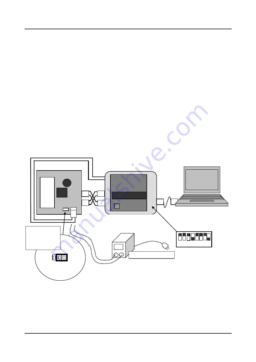
Use the following procedures to debug the software for the S1C17W23 and create an evaluation environment.
< Debugging the software >
(1) With the dedicated cable that comes bundled with the S5U1C17001H (ICDmini), connect the 4-pin connector
for connecting the ICDmini target and the 4-pin connector for the power supply for writing to the flash
memory to the CN2-1 (J5) and CN2-2 (J3) connectors, respectively, on this board.
(2) Connect the jumper switch for selecting the operational power supply (JP5) to the “EXT” side.
(3) Supply electric power from either the S5U1C17001H2 (ICDminiVer.2) or the stabilized power supply to the
CN3 (J4) power supply connector header on this board. Ensure that the supplied power voltage is within the
operational power supply voltage range for the S1C17W23. (This voltage range is between 1.8 V and 3.6 V
when programming is performed on or data is written to the built-in flash memory in the S1C17W23.)
(4) Connect the ICDmini and the PC with the USB cable that comes bundled with the ICDmini.
Set the SW4 and SW5 DIP switches (DSIO signal level selection) on the ICDmini so that the DSIO signal level is
equal to the input voltage from the target. If you are using the S5U1C17001H2 (ICDminiVer.2) emulator and the
voltage for erasing data from or performing programming on the flash memory is supplied from the ICDmini, set
the SW8 DIP switch (selection of the voltage for programming the flash memory) to ON.
Figure 1.1 Connection method for debugging the software
S5U1C17001H
For connecting
the target
For power supply
for writing to the
flash memory
USB cable
JP5
EXT
B
AT
Jumper switch for
selecting the
operational power
supply (JP5)
This board (S5U1C17W23T)
ICDmini(S5U1C17001H)
CN3 (J4)
* Use either the power supply for
ICDminiVer.2 or the stabilized power
supply.
Stabilized power supply
1 2 3 4 5 6 7 8
Settings for the DIP
switches on the ICDmini
* SW8: To supply the
voltage for erasing data in
or performing
programming on the flash
memory from the ICDmini,
set this DIP switch to ON.
OFF
ON
CN2-2(J3)
C
N2-1(J5)


